background image

INST

ALL

A

TION 

MAN

UAL


Caution 


1) Installation angle 
Please install the module at the angle having the most annual cumulative amount of solar radiation in the applicable site.  
 
2) Confirmation matter        
To improve module's electrical insulation and durability, the back side [Junction Box] of module should be protected to avoid exposure to moisture, and PV module 
wiring should be installed considering thermal expansion due to ambient temperature and vibration due to wind. When a PV module is installed on a roof, between 
the back side of the PV module and roof is maintained at a sufficient distance(minimum above 2 inch) to be well ventilated. According to the laws of the applicable 
site, the PV module can be installed on a fire resistance roof. The PV module's fire rating is "C“. 
 
3) Installation hole 
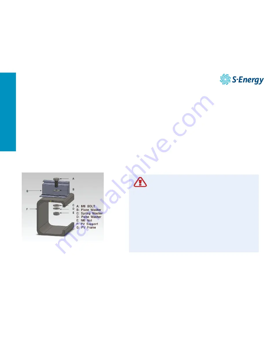
The  method  of    installing  a  frame  hole  passed  a  mechanical  load  test  item  in  accordance  with  the  IEC61215  standard,  and  S-Energy  Co.,  Ltd.  recommends  the 
following  method  of    installing  a  frame  hole.  As  described  in  figure  1,  an  installation  hole  is  inserted  in  the  frame,  if  the  frame  is  randomly  processed  or  the 
installation hole is changed, the module will be damaged or the strength of frame will be declined. 

| Hole Installation | 

Bolt Torque: 16Nm ~ 20Nm [Newton-meters] 
 
60series Bolt size: M6  L16 Bolt, [PV Support T: ≤4mm] 
72series Bolt size: M6  L20 Bolt  

 How to use a frame installation hole  

1) Be careful to avoid sealing the gap between the module and the structure, 

because the area should be well ventilated. The module of power 
performance and life can be affected, if the space between the module 
and structure is sealed. 
 

2) Please leave a space between the modules because the module can be 

expanded or be shrink depending on the ambient temperature. 
 

3)  In case of failure to use the accessories recommended by S-Energy Co., 

Ltd., it may affect the long term reliability of the module, and S-Energy Co., 
Ltd.  do not take any responsibility for life-shortening of the module 
resulting from such use. 

Summary of Contents for SN245P-10

Page 1: ...INSTALLATION MANUAL INSTALLATION MANUAL PV Module Installation SN Model Version 1 0 2015 INSTALLATION MANUAL...

Page 2: ...and the actual installation use operation and maintenance should be performed by qualified personnel with electrical license 4 For the detailed quality warranty policy of the product please refer the...

Page 3: ...20 year s manufacturing technology and thorough quality management We S Energy Co Ltd will reward our customers by continuing to develop and produce good quality of product and consistently challenge...

Page 4: ...care is required for preventing corrosion contamination deterioration due to mishandling when you load outdoor load installation Store a module in an indoor warehouse before installing Always wear pr...

Page 5: ...ool on the module frame and surface Abrasion of the coated surface may lead to oxidize frames or reduce their strength The scratch of the surface may be the main cause of the module output degradation...

Page 6: ...tall on the vehicle car train etc or ship please request special modules 12 Snow water dust or other foreign substance on the surface may increase reflection of the light and eventually reduce the PV...

Page 7: ...d by S Energy and return it to S Energy for repair and replacement Material All the wire for the PV module connection should be configured with PV cable only Cable for PV double insulation UV resistan...

Page 8: ...on should be designed to satisfy the mechanical load of the site Operating temperature A ambient temperature of module installation site is limited by the minimum and maximum temperature as shown belo...

Page 9: ...the IEC61215 standard and S Energy Co Ltd recommends the following method of installing a frame hole As described in figure 1 an installation hole is inserted in the frame if the frame is randomly pro...

Page 10: ...245 W 250 W 255 W Short Circuit Current Isc 8 85 A 8 86 A 8 93 A Open Circuit Voltage Voc 37 3 V 37 3 V 37 6 V Module Effeciency 15 00 15 30 15 61 Operating module temperature Maximum System Voltage M...

Page 11: ...method is recommended by S Energy for the installation of the PV module on a roof in heavy snow regions Failure to remove accumulated snow on the PV module for long time may cause long term power redu...

Page 12: ...ion and method of clamp installation Module Clamp Assembly 3 Additional Grounding Methods Grounding lug Clamp installation location A position Confirm 7 mechanical installation module drawing Clamp wi...

Page 13: ...orn Germany Tel 49 6196 9540 111 3 Fax 49 6196 9985 778 E mail info europe s energy com SEAI America Inc dba S ENERGY America Address 18881 Von Karman Ave Suite 760 Irvine CA 92612 U S A Tel 1 949 281...

Reviews: