RCJ21-3500
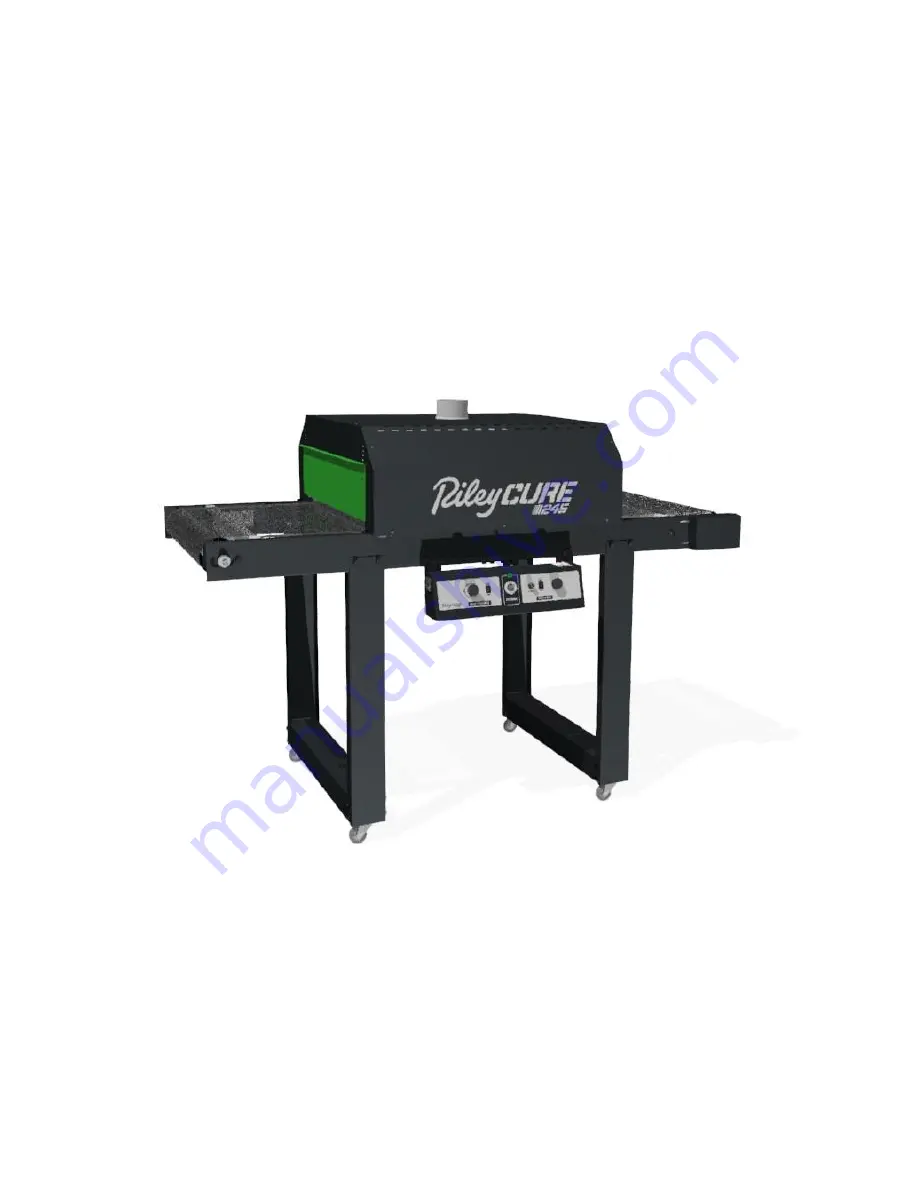
Conveyor Dryer
24
” wide by 5’ long conveyor dryer
Document # 16-514
Serial Number: _______________________________ Date: ___/___/________
(Record your machine’s serial number and date of purchase for future reference)
Page 1: ...0 Conveyor Dryer 24 wide by 5 long conveyor dryer Document 16 514 Serial Number _______________________________ Date ___ ___ ________ Record your machine s serial number and date of purchase for future reference ...
Page 2: ...from the dryer Extreme caution is necessary when any dryer is used by or near children or disabled persons and whenever the heater is left operating and unattended Do not operate any heater after it malfunctions Disconnect power at service panel and have heater inspected by a reputable electrician before reusing Do not use outdoors To disconnect dryer unplug from power source or turn off power to ...
Page 3: ... Panel RCJ21 3500C 1 1 1 1 2 Assembly Instructions Heating Chamber 4 inch Duct Start Collar 4 inch Duct 2 feet long End Shield WARNING Note DO NOT plug the equipment in or apply power until instructed to do so Note The Riley Cure 245 requires a dedicated 240 Volt 20 Amp circuit Any attempt to operate the Riley Cure 245 without the cord plug provided by the manufacturer will void the warranty Acces...
Page 4: ...the bed assembly together using 4x Hex Head Bolts Figure 1 5 Insert the Tabs on the Caster Assembly into the slots on the Leg Cross Brace then squeeze the Cross Brace to hold the Caster in place See Figure 2 6 Slide the Leg over the end of the Leg Cross Brace seating the slot in the Leg to capture the Tab on the Caster 7 Align the thru holes with the insert nuts and install the Hex Head Bolts 8 Re...
Page 5: ...Figure 2 9 Place the Leg Assemblies over the Conveyor aligning the thru holes of the Leg Assemblies with the insert nuts of the Conveyor 10 Install the eight Hex Head Bolts See Figure 3 Figure 3 ...
Page 6: ...ge guide with the roller drum grooves 4 Pull the ends of the belt together meshing the teeth of the splice while a second person reinserts the splice pin removed earlier into the channel formed by the interlocked metal teeth It may be easier to rotate the belt so that the splice is on top of the conveyor bed before inserting pin Using needle nose pliers fully insert the pin until it is centered 5 ...
Page 7: ...nstallation 1 Using two Hex Head Bolts to fasten the Control Panel to the Conveyor Assembly See Figure 5 Figure 5 2 Insert drive motor plug into drive motor receptacle Twist plug to lock in place See Figure 6 Figure 6 ...
Page 8: ...re 7 The chamber should rest flatly on the conveyor bed Figure 7 3 Insert the Duct Start Collar into the hole in the top of the Heating Chamber See Figure 8 Once in position bend the tabs at the base of the collar outward to secure it in place Place the two foot section of 4 diameter Duct onto the Duct Start Collar 4 Place End Shields at desired height on the entrance and exit of the Heating Chamb...
Page 9: ...Figure 8 ...
Page 10: ...d Bolts to fasten the Control Panel to the Conveyor Assembly See Figure 9 Figure 9 2 Insert Drive Motor Plug into Motor Extension Cord Receptacle Twist plug to lock in place See Figure 9 Insert Motor Extension Cord Plug into Drive Motor Receptacle Twist plug to lock in place See Figure 10 Figure 10 ...
Page 11: ...or bed See Figure 11 The Heating Chamber Cord must be on the same side of the Conveyor Bed as the Control Panel 2 The Heating Chamber has openings on the underside rails that fit over the Hex Head Bolts See Magnified View Figure 11 The chamber should rest flatly on the conveyor bed Figure 11 ...
Page 12: ...at the base of the collar outward to secure it in place Place the two foot section of 4 diameter Duct onto the Duct Start Collar 4 Place End Shields at desired height on the entrance and exit of the Heating Chamber 5 Plug the Heating Chamber cord into the receptacle on the Control Panel See Magnified View Figure 12 Figure 12 ...
Page 13: ...he entrance and exit ends of the chamber The area should be warm Caution Heating element is exposed inside the chamber and is operating at very high temperatures Keep your hand close to the moving belt Note Some smoke vapor and odor may be noticed during initial start up due to residual material from the manufacturing process burning off the elements 7 Working temperature will be reached after a t...
Page 14: ... any tears voids separations fraying or no longer rides in the roller drum groove due to excessive wear 2 Belt tension the belt will relax over time and tension may have to be adjusted by the instructions above Troubleshooting Symptom What to Check No heat belt not moving power light is off Incoming power correct voltage Main power switch Power cord plugged in No heat belt moving power light is on...
Page 15: ...espective manufacturer s warranty if any The warranty against defects shall not extend to damage caused from any of the following Transport by carrier Corrosion Operation or use in a manner inconsistent with specifications and or operating instructions Ordinary wear accident improper installation or maintenance Alterations made to equipment in any way Dryer manufacturer shall not be liable for los...