


Page 18
BLADE REPLACEMENT
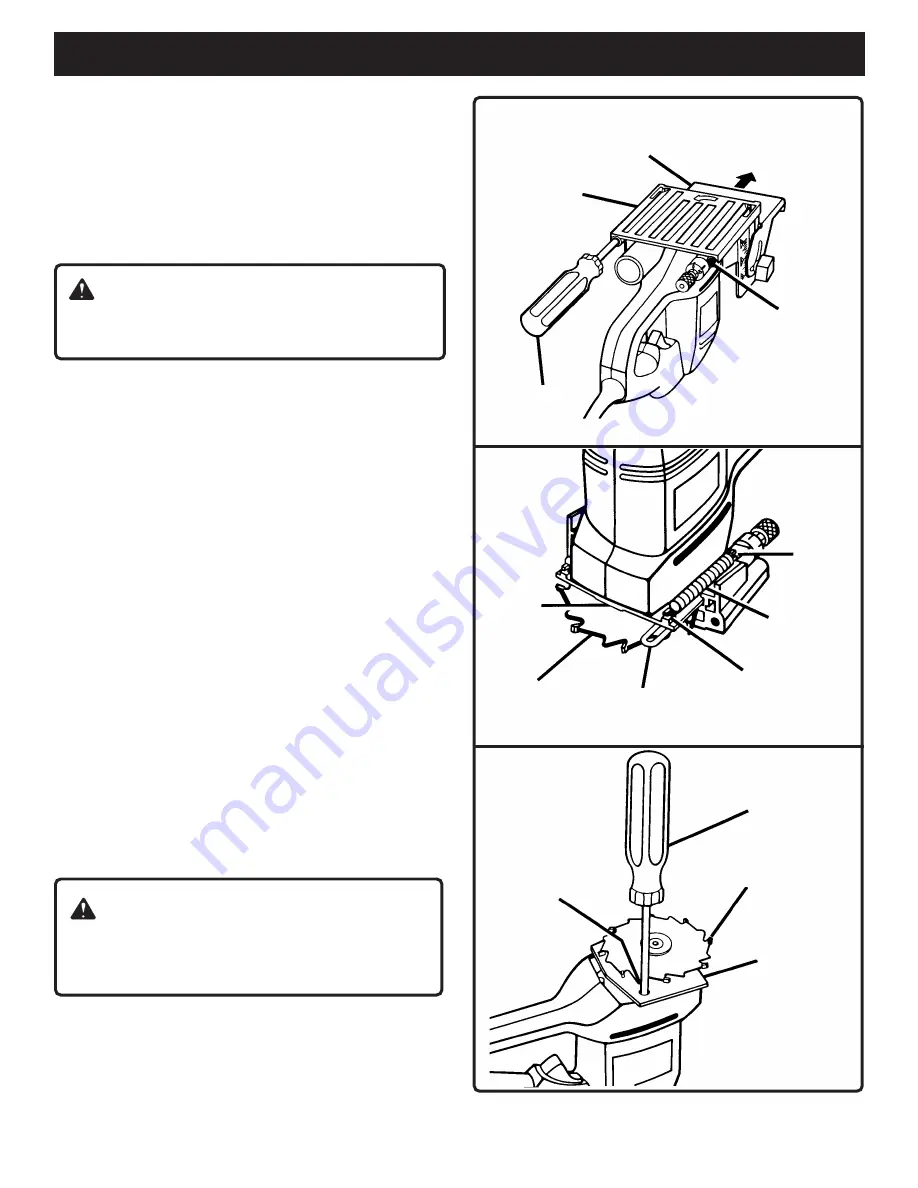
See Figures 24-27.
After extended use, the blade on your plate joiner may
become dull and need replacing. If you accidentally hit a
nail or other blunt object, it will break the carbide tips on the
blade. These situations also require replacing the blade.
HOW TO REPLACE THE BLADE
Unplug your plate joiner.
Remove dust bag.
Place your plate joiner upside down on a workbench as
shown in figure 24.
Using a screwdriver remove the two screws securing
front base assembly.
Pull adjustable fence in the direction shown by the arrow
in figure 24 and remove front base assembly.
Using a pair of needle nose pliers, stretch and release
springs from tabs on bearing plate.
See Figure 25.
Push adjustment rod away from bearing plate and
remove rear base assembly.
With base assemblies removed, place plate joiner upside
down on a workbench as shown in figure 26.
Place a Phillips screwdriver in one of the two holes
provided in bearing plate.
Place one of the non-cutting teeth located behind each
carbide tipped cutting tooth against the screwdriver or
pin and lock blade preventing it from rotating.
DO NOT
lock blade against one of the cutting teeth. Carbide
tips will break.
Using a 3/16 in. wrench, remove blade screw.
NOTE:
Turn blade screw counterclockwise to remove.
See Figure 27.
Remove outer blade washer and blade.
Clean wood particles and resin from blade washer, dust
bag area, base assembly slots, and all surrounding parts.
Place inner blade washer on gear spindle.
See Figure 27.
Place new blade onto shoulder of blade washer and
secure with outer blade washer and blade screw.
NOTE:
Blade screw fits into cupped side of outer blade
washer.
WARNING:
Failure to unplug your plate joiner could result in accidental
starting causing possible serious personal injury.
WARNING:
If inner blade washer has been removed, replace it
before installing new blade. Failure to do so could cause
an accident since blade screw will not tighten properly.
MAINTENANCE
SHOWN WITHOUT DUST BAG
Fig. 24
Fig. 25
Fig. 26
FRONT BASE
ASSEMBLY
ADJUSTABLE FENCE
TO
REMOVE
SCREW
HOLE
SCREWDRIVER
BEARING
PLATE
BLADE
ADJUSTMENT ROD
TAB (S)
SPRING (S)
NOTCH
NON-CUTTING
TOOTH BEHIND
CARBIDE TIPPED
CUTTING TOOTH
PHILLIPS
SCREWDRIVER
CARBIDE TIPPED
CUTTING TOOTH
BEARING
PLATE
Summary of Contents for JM81-1
Page 21: ...Page 21 NOTES...


