FOR QUESTIONS, CALL 1-800-345-8746 in U.S. or
1-800-265-6778 in CANADA
www.ryobi.com
IMPORTANT MANUAL
DO NOT THROW AWAY
OPERATOR’S MANUAL
2-Cycle Gas Trimmer
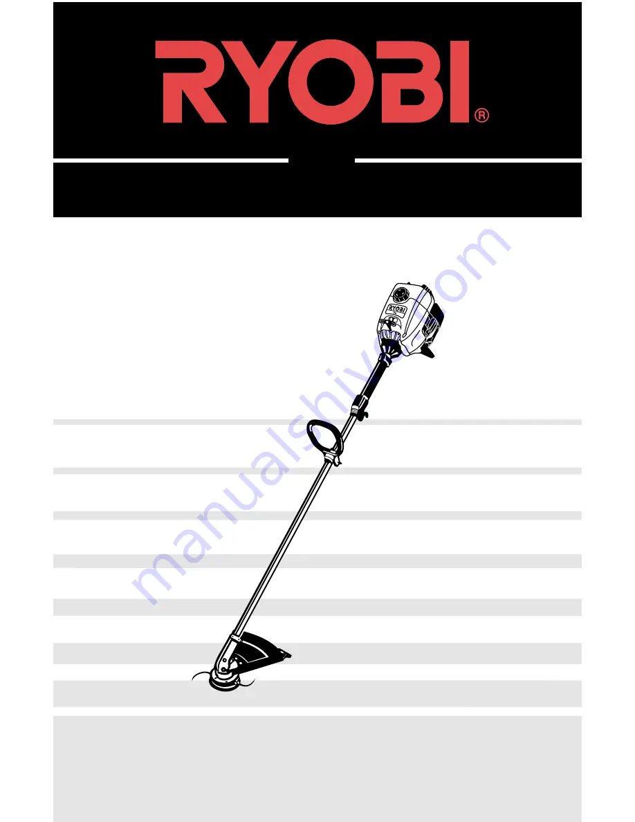
766r
Page 1: ...FOR QUESTIONS CALL 1 800 345 8746 in U S or 1 800 265 6778 in CANADA www ryobi com IMPORTANT MANUAL DO NOT THROW AWAY OPERATOR S MANUAL 2 Cycle Gas Trimmer 766r...
Page 2: ...ating this equipment THIS PRODUCT IS COVERED BY ONE OR MORE OF THE US PATENTS LISTED BELOW 5 076 149 4 901 682 4 779 405 4 651 422 4 505 040 4 463 498 4 369 742 4 342 236 4 223 441 2 125 688 D 249 012...
Page 3: ...ory equipped with a spark arrestor If these items are required in your area ask your LOCAL SERVICE dealer to install the Optional Accessory Part 180030 Spark Arrestor Kit FOR QUESTIONS CALL 1 800 345...
Page 4: ...maged in any way Make sure the cutting attachment is properly installed and securely fastened Be sure the cutting attachment shield is properly attached and positioned as recommended Failure to so can...
Page 5: ...just the D handle to your size to provide the best grip Be sure the cutting attachment is not in contact with anything before starting the unit Use the unit only in daylight or good artificial light A...
Page 6: ...ional symbols and pictographs that may appear on this product Read the operator s manual for complete safety assembly operating and maintenance and repair information WARNING READ OPERATOR S MANUAL Re...
Page 7: ...here is a sharp blade on the cutting attachment shield To prevent serious injury do not touch blade CHOKE CONTROL A FULL CHOKE position B PARTIAL CHOKE position C RUN position INDICATES OIL Refer to o...
Page 8: ...nd light weeds Decorative trimming around trees fences etc Primer Bulb Air filter Muffler Cover Fuel Cap Throttle Control Power Head Choke Lever D handle Line Cutting Blade Cutting Attachment Shaft Ho...
Page 9: ...right Bolt Grip Wing Nut Washer Fig 3 Fig 1 Fig 2 2 Insert the shoulder bolt into the squared hole in the handle Place the washer on the bolt and screw the wing nut onto the bolt 3 Rotate the D handle...
Page 10: ...shield with the holes in the cutting attachment Fig 4 Cutting Attachment Shield Shaft Housing Hex Lock Nut Fig 4 Fig 5 Cutting Attachment Shield Cutting Attachment 2 Place a hex lock nut into one of...
Page 11: ...g Blended Fuels If you choose to use a blended fuel or its use is unavoidable follow recommended precautions Always use fresh fuel mix per your operator s manual Use the fuel additive STA BIL or an eq...
Page 12: ...by idling 2 Put the On Off Stop Control in the OFF position Fig 7 STARTING INSTRUCTIONS WARNING Avoid accidental starting Be in the starting position when pulling the starter rope Fig 9 The operator...
Page 13: ...ng the line into objects such as walls or fence posts ADJUSTING TRIMMING LINE LENGTH The Bump Head cutting attachment allows you to release trimming line without stopping the engine To release more li...
Page 14: ...eing cut Where it s being cut For example the line will wear faster when trimming against a foundation wall as opposed to trimming around a tree Fig 12 DECORATIVE TRIMMING Decorative trimming is accom...
Page 15: ...he bolt inside the Bump Knob to make sure it will move freely Replace if damaged NOTE A Bump Knob Part 153066 can be purchased from your local authorized dealer 4 Use a clean cloth to clean the the in...
Page 16: ...er between the two lines to stop the lines from overlapping Do not overlap the ends of the line NOTE Failure to wind the line in the direction indicated will cause the cutting head to operate incorrec...
Page 17: ...ig 14 Pg 15 Push the inner reel and outer spool together While holding the inner reel and outer spool grasp the ends and pull firmly to release the line from the holding slots in the spool 7 Hold the...
Page 18: ...Apply enough clean SAE 30 oil to lightly coat the filter Fig 24 5 Squeeze the filter to spread and remove excess oil Fig 25 Air Filter 3 Wash the filter in detergent and water Fig 23 Rinse the filter...
Page 19: ...The cutting attachment will be spinning during idle speed adjustments Wear protective clothing and observe all safety instructions to prevent serious personal injury If after checking the fuel mixtur...
Page 20: ...cracked fouled or dirty spark plug Set the air gap at 0 020 in 0 5 mm using a feeler gauge Fig 27 CAUTION Do not sand blast scrape or clean electrodes Grit in the engine could damage the cylinder 4 In...
Page 21: ...re the unit out of the reach of children LONG TERM STORAGE If the unit will be stored for an extended time use the following storage procedure 1 Drain all fuel from the fuel tank and drain into a cont...
Page 22: ...switch to ON Fill fuel tank Press primer bulb fully and slowly 5 7 times Use starting procedure with choke lever in the RUN position Pg 12 Drain fuel tank Add fresh fuel mixture Replace or clean the...
Page 23: ...uretor Diaphragm All Position Starter Auto Rewind Muffler Baffled with Guard Throttle Manual Spring Return Fuel Tank Capacity 18 oz 530 ml Fuel Tank HD Polyethylene DRIVE SHAFT STRING HEAD Drive Shaft...
Page 24: ...NOTES 24...
Page 25: ...he engine or equipment is delivered to the retail purchaser The manufacturer warrants to the initial owner and each subsequent purchaser that the engine is free from defects in material and workmanshi...
Page 26: ...tion this warranty does not cover A Tune ups Spark Plugs Carburetor Adjustments Filters B Wear items Bump Knobs Outer Spools Cutting Line Inner Reels Starter Pulley Starter Ropes Drive Belts RYOBI res...