background image

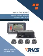
1080P HD 360° CAMERA SYSTEM

WITH BUILT-IN RECORDING

RVS-77555

Instruction Manual

VEHICLE SAFETY - 
IT'S ALL WE DO.

TM

Summary of Contents for RVS-77555

Page 1: ...1080P HD 360 CAMERA SYSTEM WITH BUILT IN RECORDING RVS 77555 Instruction Manual VEHICLE SAFETY IT S ALL WE DO TM ...

Page 2: ... Standard Configuration 6 4 Specifications 7 5 Wiring Diagram 8 6 Operation Instruction 9 6 1 RemoteControl 9 6 2 User Interface Setup 6 7 System Contents 25 8 Installation Calibration 26 9 WebApp Operating Instructions 35 10 FAQs 40 Table of Contents ...

Page 3: ...edspaces areaswithexcessivevibrationorsubjectto severeimpacts 6 Neverpuncture scratchoruseabrasivecleaningmaterialsonthisdevice 7 Donotplacecableswheretheymaybepinchedorsteppedon 8 TheControlBoxisnotdesignedtobewaterproof OperatingPrecautions 1 Thedevicemaybepoweredbya12or24voltautomotivebatteryorvehicleelectricalsystem 2 Makesureallcablesareconnectedproperly Observepolarity Impropercableconnectio...

Page 4: ...resenceofuninsulated dangerous voltage withintheproduct senclosurethatmaybeofsufficientmagnitudeto constituteriskofelectricshocktopersons Thissymbolisintendedtoalerttheusertothepresenceofimportantoperatingand maintenance servicing instructionsintheliteratureaccompanyingtheappliance Thissymbolisintendedtoalerttheusernottodisposeofelectricalandelectronic equipment CAUTION Youarecautionedthatanychang...

Page 5: ...developmentofbuilt inhighperformance H 264videoencoding decodingengineercoremakeitefficienttocompositehighaccuracy seamlessimages 3 Supports4pcs x128GSDcardsforrecordingstorage 4 Low costcalibrationtools simplifiedcalibrationprocedures 5 Maximum4CH1080P 30FPSvideoresolution 6 Highdefinition1080PHDMIvideooutput 7 Simplifiedinstallationsteps easyautostitching 2 2Application 2 Features ...

Page 6: ...ft rightwireistriggered 6 Installationguidewithpictures 7 Automaticplanecorrection 8 SupportsRecording 3 StandardConfiguration ITEM CONFIGURATION QUANTITY 1 Main control box 1 2 Full HD fish eye camera 1 3 Remote control 1 4 Infrared extension cable 1 5 Main harness 1 6 Power Cable 1 7 Wi Fi Antenna 1 8 20M extension cable for HD camera 4 9 HDMI extension cable 1 10 Monitor 1 ...

Page 7: ...Vehicle Safety It s All We Do TM 7 2 CameraParameter 4 Specifications 1 MainControlBox ...

Page 8: ...Rear View Safety 8 5 WiringDiagram ...

Page 9: ...imagechanneltoleft right view oroperateplus minusinmainmenuinterface P P UP DOWN Front backbutton Shiftimagechanneltofront backview VIEWMODE SHIFT SamefunctionasTabbuttontoshiftcurrentchanneltofull screendisplayorexitfromfullscreendisplay It susedfor switchingmenuselectioninmainmenuinterface ON OFF POWER Turnon offvideodisplay Numberbutton0 9 0 9 Inputnumbers CLEAR Backspacebutton Deleteacharacter...

Page 10: ... Returntolastmenu Note 1 Initialpassword 000000 Pleasemodifypasswordafterstitchingisfinished 2 Ifpasswordisforgotten input root tologin SelectfactorydefaultsettinginInformation menuandnewpasswordwillbe000000 3 Theoperationperiodlastsfor10minafterlogin Passwordmustbeinputagainoncetime outorafterrestartdeviceorinsleepymode PasswordReset ...

Page 11: ...nandsystemlogmanagement 4 DVR Recordingfunctionconfiguration 5 AVM 360panoramacalibrationandrelatedoperation 6 Player Videofileplaybackandprocessing 7 Information UpgradeoperationandlocalIPsetting 8 Radar Radarconfiguration Note 1 WhenUARTisconfiguredasnon Radar theRadaricononthemaininterfacewillbehidden 2 Recordingbecomesinvalidwhenenteringplayermenu 3 0 9NumericKeysonremotecontrolsupportQuickPos...

Page 12: ...atiobetweenBirdViewandSingleView 8 FrontCursor Frontviewcursorselection 9 SurroundViewMode Surroundviewmodeselection 10 UARTFunction UARTfunctionselection 11 Exitthecurrentinterfaceandreturntothemainmenuinterface Operationdescription 1 TABkey Shiftinmenu 2 Left rightorUp Down Changetheselectedfunctionitemparameters 3 ESCkey Shortcutkeyforexit returntothemainmenu 1 Whensettheradarfunctionon itisrec...

Page 13: ... Do TM 13 FeatureDescription 1 Setcalendartime 2 Savesetuptime 3 Exitmenuandreturntothemainmenu Menusettingchangemustbesavedtobecome 6 2 5Storage FeatureDescription 1 FormatSDCardorUDisk 2 Selectallsystemlogfiles 6 2 4ClockSetup ...

Page 14: ...ay interfaceandStoragemenuinterface SeetheStorageStatemenuundertheStorageMenuforspecific errorreasons 2 DonotremovetheUDiskwhenperformingUDiskrelatedwriteoperations suchasUDiskformatting exportingsystemlogs andexportingstitchingresults 3 Do not remove the SD Card when performing an SD Card related write operation such as when the recordingisnotstopped theSDCardisformatted orthesystemlogiscleared 4...

Page 15: ...tionSetup 5 Backtoparentmenu Note 1 Gaugeiscmbydefault Thestitchingresultwillbepromptedbythepopupwindow 6 2 7 AVMCalibration 4 Poweronautomaticvideorecordingfunctionsetting 5 Savesettingparameters 6 ExittheDVRinterfaceandreturntothemainmenu Ifanyparameterismodified itmustbesavedbeforeexit otherwisethemodificationisinvalid Note Whenparametersaremodified savingorexitwillprompttorestart ...

Page 16: ... Deleteinput 3 Capitalshift 4 Letterlock Note 1 Letterlockislockedbydefault Unlocktoinputcharacters 2 Lettercanonlybeinputviasoftkeyboard ChessBoard FeatureDescription 1 Layoutsettingofcalibrationcloth 2 Save Note Layoutsettingshouldbecompliantwithrealcalibrationcloth ...

Page 17: ... 17 AVMOptionSetup FeatureDescription 1 UploadcalibrationfilesofUDisktosystem 2 Outputsavedcalibrationfilesand4CHsingle viewtoUDisk 3 Changevehiclemodels 4 ExitKey GetbacktoAVMCalibrateinterface Note CalibrationfileappliesXMLextension ...

Page 18: ... FeatureDescription 1 SelectuploadedfileswithXMLextension 2 ConfirmselectedfileswithXMLextension Note If the preference of uploaded file is empty please select files with XML extension from the expand list OncethechangeofXMLfilesconfirms youaretobepromptedtorestartthesystemeithersaveorexit ...

Page 19: ...ser definedvehiclemodelpicture 3 Saveselectedvehiclemodel Ifchanges willbepromptedtorestartthesystem Note 1 User definedvehiclemodelshouldbeinformatofPNG SettingDescription 1 Confirmoutputfiles Note 1 Beforeoutput makesureUDiskisconnectedandfunctioningnormally UDiskshouldn tbepulled outduringprocessing 2 Aftersuccessfullyoutputfiles nameitwiththetimeanddateofthesystem ...

Page 20: ...endarlist Greenhighlighteddatesrepresentvideofilesofcurrentdate Pressreturnkeytoget backtoplayerinterface 2 Timelist Greenrepresentsvideofilesofcurrenttime Presscancelkeytogetbacktocalendar 3 Videolistandcontrolkey All none delete export playkeytooperatevideosettings ...

Page 21: ...ng player Pleasenotethetimingforplayer Recordingwillbeautomaticallyrecoveredonceexitstheplayer 2 Systemcanonlysearchandplayvideosrecorded3monthsbeforethesystem scurrentdate FeatureDescription 1 Controlbuttonandprogressbarforplayback Note 1 PageUp PageDowncanonlyswitchplaybackvideosamongtheselected 2 CLEARKeysupportHide showiconofplaybackcontrolbutton ...

Page 22: ...x x xx tar gzunderU Diskrootfile 2 FirmwareVersion CurrentMCUFirmwareversioninformation upgradefileslist upgrade confirmationkey Thisfunctionisactivatedonlywhenthere sMCUupgradefile HD360 MCU APP 00 Vx x xx binunderUDiskrootfile 3 IPSetup Do not pull out U Disk during system upgrade There will be a indication red dot on upgrade key if there snewAPPsoftwareorMCUfirmwareversionunderUDiskrootfile ...

Page 23: ...orradardetectsobstacleswithindangerousrange 0 6m 1 Channel and Sensors Each channel uses 3 sensors Red sign flickers when sensor detectsanyobstacleintherange Ifcombine selectcurrentlyeditedlocationsofradarsensor theirrep resentedredblockswillflicker 2 Selectontoenablesensortoworkandofftodisable Detectionrangeisconfigurable from0 6mto5m 3 Savesettingsofselectedradarsensors 4 Restoretotheinitialdefa...

Page 24: ...npositionuptomakeitcapturemoreviews 2 Therectangularzebra tapeshouldbelaidascloselyaspossibletothevehiclebody Different sized vehicleshavedifferentrectangularsize 3 Thecamerasshouldbemountedtothevehiclebodyascloselyaspossibletocaptureasmallpart ofthevehiclebodyandthezebra tape tryingtoavoidusingmagneticbasesorotherthickbrackets The lensofthecameracanbechangedaccordingly 4 Begin the calibration und...

Page 25: ...Vehicle Safety It s All We Do TM 25 7 SystemContents Controlbox MainWireBundle IRExtensionCable 1080PHDMonitor HDMIAdapterCable WEBAPPTransmitter CameraExtensionCable RemoteControl Camera PowerCable ...

Page 26: ...unitof360system Themainunitisusuallyputinthecentralcontrolroomorbehindthetoolbox Step2 Installingcameras Choosepropercameraposition Drillholesthatfitthesizeofregularassemblies Fixthefronthousing Fixthebackandfronthousing together Not too tight so that youcanadjustcameraangleif necessary ...

Page 27: ...Vehicle Safety It s All We Do TM 27 Step3 InstallingCameras Adjustcameraangleonebyone Thenscrewittightly Makesuretheoriginalimagemark whitedotoncameras areplacedoutward Properangleofcameras ...

Page 28: ...ayed on the screen Surround view is on the left and single view on the right Single view could be switched by remote if needed Step 7 Debug the image calibration For details please refer to the Calibration Steps in next pages CalibrationSteps Step 1 Lay a rectangular frame around the vehicle Laythelinesparallelandascloseaspossibletothevehiclebodywhilemakingsureeachlinecould completely be shown in ...

Page 29: ...e front back cameras are mostly installed in the middle While position of the mats in the right left can be adjusted as long as the mats are completely shown in the image it is suggested to put middle point of the mat just below the camera Measure the length of the rectangular frame width of the rectangular frame and chess posi tion length from middle point of the left right mat to the back ...

Page 30: ...r small vehicle system You could also use other mats and set up the grid size accordingly Enter chess board interface to check whether figures are the same as the grid numbers of the mats That is grid black white number at long side x number at short side Center means the chess board in the middle while edge means the chess board on the left or right Click to start automatic stitching ...

Page 31: ...ound calibrateonestep 2 Onechessboardfound calibrateexitonly 3 Nochessboardfound Ifstate1 isindicated thechannelissuccessfullycalibratedtothearoundview Ifstate2 or3 isindicated youmayneedtocheckwhetheranymathasbeenshadedorwhetherthe blackandwhitegridshavebeenblurredduetoimproperlight Click torestartautomaticstitching OnlywhenState1 isindicatedfor4channels thecalibrationiscompleted ...

Page 32: ...Rear View Safety 32 Calibration Mat Chosen and Laid ...

Page 33: ...Vehicle Safety It s All We Do TM 33 CalibrationMatChosenandLaid ContinuedTable1 ...

Page 34: ...Rear View Safety 34 Calibration Mat Chosen and Laid ContinuedTable 2 ...

Page 35: ...ection Step1 Afterthe360systemispoweredon turnon WLAN ofthemobilephone searchforwifisignal stonkamavs andconnecttoit Passwordis 12345678 Step2 Openbrowser enter 192 168 30 1 intheaddressbarandaccessandentertheWebAPP operationinterface Theupperhalfoftheoperationinterfaceisacontrolkeyboard whichisequalto theremotecontrolbuttonfunction Thelowerhalfarearefreshesthecurrentdisplayscreenofthe360 systemin...

Page 36: ...at the far right of the menu bar to open or close the video download page 2 Calendar list Yellow highlighted dates represent video files of current date Only dates in yellow could be selected Also dates could be switched by clicking the or icon 3 Time list Yellow represents video files of current time ...

Page 37: ... Thedownloadfunctionisonlyavailablewhenthereisvideofileinthe360roundviewsystem Inotherwords theSDcardmustbeinsertedandthereisvideofileintheSDcard 9 3 2SystemSetup 1 Selectthecorrespondingconfigurationinthesystem andclickthesub mitbuttonatthebottomofthepagetosubmittheconfiguration Note 1 Aftertheconfigurationissubmitted the360systemmustberestartedtotakeeffect ...

Page 38: ...Rear View Safety 38 9 3 3 AVM Calibrate Feature Description 1 Panoramastitchingparametersettings Thisfunctionisequaltothe AVM Calibrate interface on the system interface ...

Page 39: ...Vehicle Safety It s All We Do TM 39 9 3 4DVRSetup 9 3 4VersionImportAndExport FeatureDescription 1 Recordingfunctionrelatedsettings Thefunctionisequaltothesystem s DVRSetup interface ...

Page 40: ...ccurate make sure that the calibration cloths are laid smoothly enough and check if the procedures of laying calibration cloths meet the requirements of chapter 6 1 Q3 Some camera appears upside down or left right reversion It s mainly caused by having selected wrong directions during camera installation Please check if the camera is installed correctly and recalibrate if needed Q4 After stitching...

Page 41: ...Vehicle Safety It s All We Do TM 41 NOTES ...

Page 42: ...If you have any questions about this product contact RearViewSafety Inc 1797AtlanticAvenue Brooklyn NY11233 800 764 1028 VehicleSafety It sAllWeDo TM ...

Reviews: