background image

9

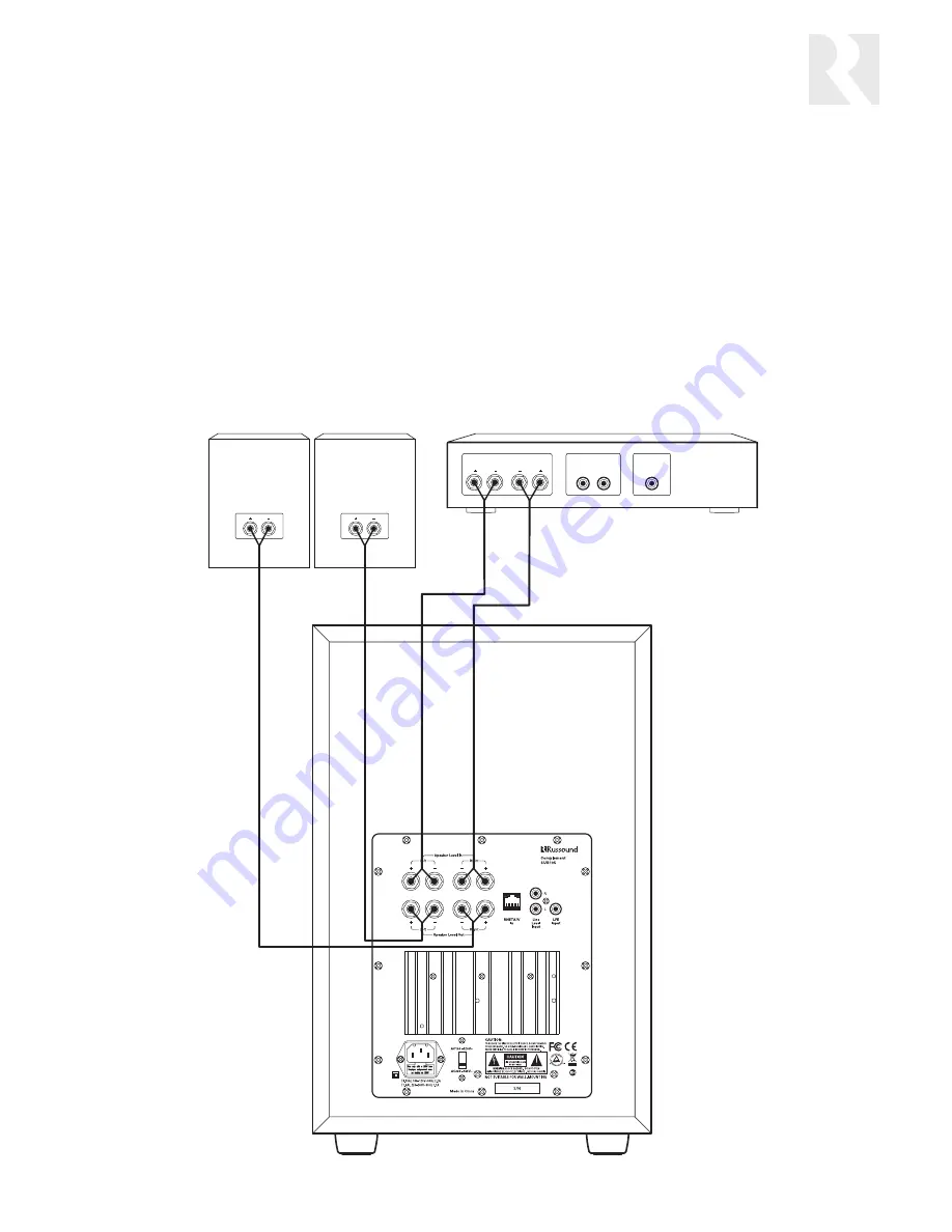
Speaker-level input

This input is for use when you need to send an amplifi ed 
signal to the SUB105, such as when no line-level signal 
is available.

Use stranded copper speaker cable to connect between 
the SUB105’s speaker-level input terminals and the 
front left and right speaker terminals on the receiver or 
amplifi er. The binding posts accept single banana plugs, 
spade lugs, pin connectors, and bare wire up to 12 AWG 
(2.05 mm).

Be sure to observe proper polarity. For speaker cable 
with red and black wires, connect the red wire to the 

red positive (+) terminal and the black wire to the black 
negative (–) terminal.

Note:

 Some speaker cables have other ways of desig-

nating polarity. For example, cable with a clear jacket 
usually has a copper-colored wire for positive and a 
silver-colored wire for negative. In a cable with white 
and black wires, the white is positive and the black is 
negative. Cable with both wires the same color may 
have grooves, ribs, or stripes on the positive wire.

When you use the speaker-level input on the SUB105, 
you can connect the main left and right speakers to 
the corresponding output terminals. The full-frequency 
signal will pass through to the main speakers.

Speaker Outputs

Line Level Output

Left Right

Left Right

LFE Output

Receiver

Left speaker

Right speaker

SUB105

Connection using speaker-level input with pass-through to main speakers

INSTALLATION

Summary of Contents for Complement SUB105

Page 1: ...Complement SUB105 Powered Subwoofer Instruction Manual ...

Page 2: ... appliance should not be situated on a bed sofa rug or similar surface that may block the ventilation openings or placed in a built in installation such as a bookcase or cabinet that may impede the flow of air through the ventilation openings 9 Heat The appliance should be situated away from heat sources such as radiators heat registers stoves or other appliances includ ing amplifiers that produce...

Page 3: ...oofer s location affects how stand ing waves are created correct subwoofer placement is important to avoid such peaks and nulls They can t be fixed by equalization which could overdrive the speaker and amplifier causing distortion or damage The first step toward getting accurate bass response is to set the subwoofer s crossover to match the low fre quency roll off point of the main speakers Once y...

Page 4: ...nectors and bare wire up to 12 AWG 2 05 mm RNET A V IN RJ 45 connector for a balanced stereo line level signal via CAT 5 cable from an RNET A V source output or an RNET A V Encoder LINE LEVEL INPUT RCA connectors for stereo line level signals from a preamplifier or receiver LFE INPUT RCA connector for a prefiltered low frequency effects signal from a home theater receiver or processor VOLTAGE SWIT...

Page 5: ...elects the power state of the internal amplifier Set to Off to keep the SUB105 off Auto to turn it on only when it senses an au dio signal or On to keep it turned on all the time CROSSOVER FREQUENCY CONTROL Selects the frequency for the low pass filter within the range of 50 to 200 Hz PHASE SWITCH Allows the speaker phase to be inverted to improve acoustic response in some situations Set to 180 to...

Page 6: ...for use when the LFE or subwoofer output on the home theater receiver or processor is turned on Connect an RCA patch cable between the SUB105 s LFE input and the LFE or subwoofer output on the receiver or processor Note The LFE input is not connected to the SUB85 s internal low pass filter Accordingly the crossover frequency control has no effect on a signal entering this input Use the LFE input o...

Page 7: ...sor Note When the LFE or line level input is connected to an audio system powered by a different electrical circuit from the one used to power the SUB105 a ground loop may result This causes a low frequency hum To eliminate the hum connect the SUB105 to the same electrical circuit as the audio system or use a ground loop isolator in series with the RCA cable Connection using stereo line level inpu...

Page 8: ...t the source end plug the connector into the RNET A V jack on the source or the RNET A V Encoder At the SUB105 plug the connector into the RNET A V jack If desired use a modular wall plate and an RJ 45 patch cable for a neater appearance Punch down the CAT 5 per the T568A standard and use a straight through patch cable between the SUB105 and the wall plate RJ 45 Using T568A Wiring Standard SUB105 ...

Page 9: ...k negative terminal Note Some speaker cables have other ways of desig nating polarity For example cable with a clear jacket usually has a copper colored wire for positive and a silver colored wire for negative In a cable with white and black wires the white is positive and the black is negative Cable with both wires the same color may have grooves ribs or stripes on the positive wire When you use ...

Page 10: ...ibration CD or DVD and a sound level meter Volume Start with the volume set at minimum raising it gradu ally until output from the SUB105 sounds about the same volume as output from the main speakers Again you can use a sound level meter to be precise Phase Depending on the location of the SUB105 its output at certain frequencies may be out of phase with the output of the main speakers This is esp...

Page 11: ...rotect the unit from damage in transit Before returning a speaker for repair call Russound at 603 659 5170 for a Return Authorization number Write the RA number on the shipping label and ship to Russound ATTN Service 5 Forbes Road Newmarket NH 03857 Russound sells products only through authorized Dealers and Distributors to ensure that customers obtain proper support and service Any Russound produ...

Page 12: ... 5170 Fax 603 659 5388 www russound com Technical Support tech russound com 28 1282 08 10 07 Copyright 2007 Russound All rights reserved All trademarks are the property of their respective owners Specifications are subject to change without notice Russound is not responsible for typographical errors or omissions ...

Reviews: