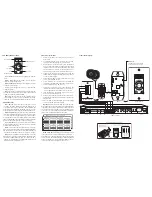
Connection Diagram
/
/
/
/
Connection Instructions
Ensure it is possible to run the wire to the location you
1.
have chosen.
To install the keypad, you will need to use a UL/CSA
2.
approved plastic single-gang (18 ci) electrical box.
Route CAT-5 wire to the electrical box from the CA4 Wall
3.
Port. The cable length from the wall port to the keypad
should not exceed a total of 240'. Mark the cables with
the zone number or location. Use the supplied 6' CAT-5
patch cables to connect the controller to the wall port.
Terminate the CAT-5 wire with a RJ-45 plug using the
4.
T568A standard configuration. Plug the wire into the jack
on the rear of the keypad.
Ensure the 2-pin jumper is in the off position (on one pin
5.
only) or removed from the pins.
Source labels must be inserted prior to installing the
6.
trim plate on the keypad. Determine the system’s source
names and numbers. (e.g., CD, Source 1).
Select the corresponding source name label from the
7.
included label sheets. Left-side labels are used for sources
1 and 3; right-side labels are used for sources 2 and 4.
Slide the label into the window slot until the source
8.
name is centered in the window.
Push any extra cable back into the wall or electrical box.
9.
Align the keypad back plate and screw the keypad to the
electrical box.
Place the foam around the keypad face, and then align
10.
and screw the trim plate to the keypad.
Important:
All four connections from the controller to the
wall port must be made, even if there are less than 4 keypads
connected to the system. Cables between the wall port and
the controller must match numerically (#1 on the wall port
to #1 on the controller). Swapping cables between wall port
jacks and the controller may damage the system.
CA4-KP Keypad Operation
Source Indicators:
Indicates source playing or User Menu
option.
Volume Level:
Indicates the volume level or indicates
User Menu option settings status.
Volume Up/Down:
Raises/lowers zone volume or adjusts
User Menu option settings.
Source:
Cycles through the sources or cycles through
User Menu options.
Power:
Turns zone On/Off with a press, issues All ON and
All OFF with a hold, indicates system status, and provides IR
confirmation with red IR talk-back LED.
IR Receiver:
Receives and repeats IR commands to the
source equipment. Sources can be controlled with CA4-RC
system remote or with original equipment remote controls.
Keypad Functions
Power ON/OFF:
A press and release of the power, source
or volume up /down buttons will turn the keypad ON. A
second press and release of the power button will turn the
keypad and the backlighting OFF.
Note:
If there are other
keypads ON in the system the power button will remain lit.
Volume Adjustment:
Upon initial powering of the keypad,
the volume will automatically ramp up to the factory set turn-
on volume level. Pressing the volume up or down buttons
will change the volume accordingly. Volume levels will be
indicated by the LEDs above the volume up button. Hold the
buttons to ramp the volume up or down accordingly.
Source Selection:
A press and release of the source button
will cycle through the sources. The selected source indicator
will be backlit on the keypad.
All ON:
A press and hold of the power button (3 seconds)
while the zone is already in the ON state will turn all keypads
ON (if enabled to respond). The volume LEDs will light up
from the center and ramp outward.
(See usage note at right)
All OFF:
A press and hold of the power button (3 seconds)
while the zone is in the OFF state will turn all keypads OFF.
The volume LEDs will light up from the center and ramp
outward. The backlighting on all keypads will turn off and
the system will be in Standby mode.
CA4 Controller
Wall Port Front
Keypad Front
Rear
Rear
CAT-5
(240' max)
CAT-5 (6' max)
Important:
The jumper must be in the OFF
position for normal operation.
Source
Volume
Up or Down
Source Indicators
Power
IR Talkback LED
Volume Indicators
IR Receiver
All ON Usage Note:
If initiating an All ON command, all
other powered zones will automatically be placed into a
Party Mode as non-Masters and will not have independent
source selection. The initiating keypad is the Master and will
need to be turned off to discontinue the Party Mode before
source selection can be available for other zones.
- Right Side
- Left Side


