


8.2 Installing the Optional CA-LRN Learning Keypads
• Connect the CA-LRN’s Interface cable to the 16 pin header located on the
CA KP. Note the location of the red stripe.
• Mount the keypads into double gang box and attach the double gang
Decora plate.
• Skip to step 10
9. Installing the CA-LCD Keypads
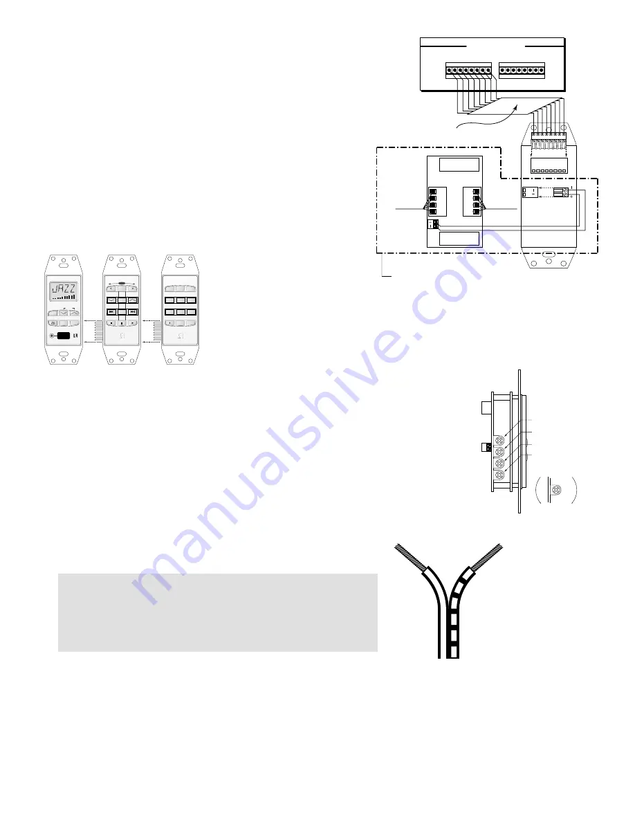
9.1 Keypad Connections (See Figure 1)
Connect each wire 1 thru 8 using a small jewelers screwdriver. Take note of the
color of each wire and the number, being sure that the color and number
match at the keypad and the keypad input on the controller. If you are using
the optional SRM-2.1 speaker relay module, wire the +, - terminals of the CA-
LCD to the SRM-2.1 +, - terminals.
9.2 Installing the Keypad (see Figure
2)
The best performance is achieved
when the keypad is placed away
from direct sunlight. Consider a
convenient operating location before wiring. Choose a place that is easily seen from the
common areas of the room. Be sure that you will be able to route the wire for the keypad for
the area you have selected. The wire should not be run or placed near AC wiring. Mount the
keypad into a standard 18 cubic inch j-box or p-ring using a Decora-style cover plate when
finished. If you are installing the optional DSC keypad you will need to use a double-gang
electrical box. If you are installing the CA-LCD, DSC and the
optional DAN keypad you will need to install a triple-gang
electrical box.
9.3 Setting the Keypad (See Figure 3)
Before the keypad is installed into the j-box, turn on the power so that you can operate the keypad. The
amber and the green backlight brightness can be individually set. Note the brightness controls are located
on the side of the keypad. Adjust to the desired brightness the backlight that first comes on. Press and
hold the lamp button on the front of the keypad until the backlight switches to the other color. Adjust the
brightness for the selected color. Also the maximum volume and the balance can be set at this time.
10. Speaker Installation
• If you are installing in-wall speakers, follow the instructions
provided with your speakers for mounting.
• Connect each speaker wire to the correct polarity (+,-).
11. Operation
11.1 Operating the Main Unit
• Power switch: When the power switch is engaged, the CA4.4pi power indicator will be lit an amber color. The CA4.4pi should be
left on at all times. The unit will consume very little power unless the zones are on and active. The unit has a stand-by mode when the
zones are inactive.
• Zone Indicators: The zone indicator will light either red for off or green for on. The zones can only be turned on from the keypads.
All functions are accessed through the keypad only.
Finally!!!
• Make sure that the voltage selector, located on the rear panel of the
CA4.4pi, is on the correct current for your country, either 110V or 220V
• Power up by plugging in all power cords and turning the CA4.4pi and
sources on.
6
-
+
CAT5 OR 8 CONDUCTOR
22AWG WIRE
1 2 3 4 5 6 7 8
I
NPUT
F
ROM
K
EYPADS
4
3
1 2 3 4 5 6 7 8
1 2 3 4 5 6 7 8
L+
L–
R
–
R
+
L +
L –
R
–
R
+
AMPLIFIED ZONE
INPUT FROM MULTI-
ZONE SYSTEM
AMPLIFIED
OUTPUT TO
IN-WALL SPEAKERS
SRM-2.1
CA-LCD
Connections for the SRM-2.1 accessory only
AMBER BRIGHTNESS
GREEN BRIGHTNESS
VOLUME
BALANCE
LESS
MORE
Figure 1
Figure 3
DIRECT ACCESS
NUMERIC SOURCE KEYPAD
8
9
7
5
6
4
2
3
1
0
ENTER
DIRECT SOURCE CONTROL
SEEK
MODE
SELECT
SCAN
REMOTE SENSOR
VOLUME
SOURCE
STORE
POWER
CA-LRN
DAN
DSC
Figure 2


