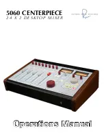
Rupert Neve Designs 5060 CENTERPIECE Operation Manual Download Page 15

15

instruments within acoustic environments that is subjectively pleasing so as to develop keen awareness 
that will contribute to a reliable data bank. Humans who have not experienced enough “natural” 
sound may well have a flawed data bank! Quality recording equipment should be capable of retaining 
“natural” sound and this is indeed the traditional measuring stick. And “creative” musical equipment 
should provide the tools to manipulate the sound to enhance the emotional appeal of the music without 
destroying it. Memory and knowledge of real acoustic and musical events may be the biggest tool and 
advantage any recording engineer may possess.

One needs to be very careful when one hears traces of distortion prior to recording because some flavors 
of distortion that might seem acceptable (or even stylish) initially, may later prove to cause irreparable 
damage to  parts of the sound (for example, “warm lows” but “harsh sibilance”) or in louder or quieter 
sections of the recording. Experience shows that mic preamps and basic console routing paths should 
offer supreme fidelity otherwise the engineer has little control or choice of recorded “color” and little 
recourse to undo after the fact. Devices or circuits that can easily be bypassed are usually better choices 
when “color” is a consideration and this particularly is an area where one might consider comparing 
several such devices. Beware that usually deviations from linearity carry at least as much long-term 
penalty as initial appeal, and that one should always be listening critically when recording and generally 
“playing it safe” when introducing effects that cannot be removed.

1.  Tsutomu Oohashi, Emi Nishina, Norie Kawai, Yoshitaka Fuwamoto, and Hishi Imai. National
Institute of Multimedia Education, Tokyo. “High Frequency Sound Above the Audible Range,Affects Brain Electric Activity and 
Sound Perception” Paper read at 91st. Convention of the A.E.S.October 1991. Section 7. (1), Conclusion.
2.  Miland Kunchur,Depart of Physics and Astronomy, University of South Carolina. “Temporal resolution of hearing probed 
by bandwidth restriction”, M. N. Kunchur, Acta Acustica united with Acustica 94, 594–603 (2008) (http://www.physics.
sc.edu/kunchur/Acoustics-papers.htm)
3.  Miland Kunchur,Depart of Physics and Astronomy, University of South Carolina.Probing the temporal resolution and 
bandwidth of human hearing , M. N. Kunchur, Proc. of Meetings on Acoustics (POMA) 2, 050006 (2008) 

Specifications

Stereo Outputs (unless otherwise specified, frequency is 1 kHz)

Max input level


Channels 1-8   , Fader at 0dB 


+25.4 dBu


Channels 9-24, Max input, level trim at 0dB 


+25.4 dBu

Max Output level


Any combination of inputs   


+25.4 dBu

THD+N

Channels 1-8, fader at unity, BW <10 Hz – 80k Hz, 
 

+20 dBu, 20 Hz 


0.03%


+20 dBu, 2 kHz 


0.003%


+20 dBu, 20 kHz 


0.02%

Channels 9-24, trim at unity, BW <10 Hz – 80k Hz
 

+20 dBu, 20 Hz 


0.03%


+20 dBu, 2 kHz 


0.004%

Summary of Contents for 5060 CENTERPIECE

Page 1: ...Operations Manual 5060 CENTERPIECE 2 4 X 2 D E S K TO P M I X E R the ...

Page 2: ...the cord exits from the apparatus 11 Only use attachments accessories specified by the manufacturer 12 Unplug this apparatus during lightning storms or when unused for long periods of time 13 Refer all servicing to qualified service personnel Servicing is required when the apparatus has been damaged in any way such as when power supply cord or plug is damaged liquid has been spilled or objects hav...

Page 3: ...Dim Ext I P Talkback Mix Out Monitor Section GND CW CW Stepped Attenuator Mono Summing Left VU StInL1 StInL1 StInR1 StInR1 Talk1 Talk2 Talk1 Talk2 GND Soft Mute Insert Return GND Soft Mute StInL1 StInL1 StInR1 StInR1 InsInL1 InsInL1 InsInR1 InsInR1 Insert Return GND Soft Mute Insert Return GND LineIn9 LineIn9 GND LineIn10 LineIn10 1 2 3 4 5 6 7 8 L INS RTN L INS SND R INS RTN R INS SND Stereo Inse...

Page 4: ...inal mix and provides 2 track outputs source selection and speaker feed outputs from the monitor section In the 5060 amplification is handled with fully class A operational amplifier topologies featuring Rupert s custom transformer designs While these circuits share a lineage with the circuits used in Rupert s consoles from the 70 s and in many ways sound similar there are refinements in noise sle...

Page 5: ...xture Limit dBu Threshold Blend Limit dBu Ratio Silk Red Silk Blue Blend Threshold Gain dB Texture Gain db Release Attack Release Attack CH A Master Depth Depth Width Width CH B CH A HF HM LM LF HF HM LM LF POWER Equalizer Comp Reverb 1 Reverb 2 Reverb 3 Delay L R L R LEVEL LEVEL PAN PAN INSERT INSERT STEREO 2 STEREO 2 10 15 3 30 20 0 10 15 3 30 20 0 MIN MAX TEXTURE MIN MAX TEXTURE STEREO 1 STEREO...

Page 6: ... 6 30 4 10 20 10 0 6 30 4 10 20 10 0 6 30 PEAK PEAK 0 MIN MAX 30 6 0 9 10 11 12 13 14 15 16 17 18 19 20 21 22 23 24 1 2 3 4 5 6 7 8 50 60 20 10 40 25 15 0 5 10 5 0 5 10 30 40 50 15 10 5 0 5 10 30 40 50 15 10 5 0 5 10 30 40 50 15 10 5 0 5 10 30 40 50 15 MIX STEREO INPUT CHANNELS 9 24 TB ASSIGN MONITOR SELECT HEADPHONE MONITOR SOURCE STEREO INPUT CHANNELS 1 8 RUPERT NEVE DESIGNS MASTER MONITOR TB LE...

Page 7: ...6ch to link the aux busses between units If you would like the same processing on both the aux path and the mix path it needs to be inserted before the line ins on the aux 5059 For the 5059s creating the stereo stems into the 5060 the configuration is identical to the 5059s Mixing into a 5060 example HOW TO CALIBRATE FOR A DIGITAL MIX IN ANALOGUE For engineers looking to completely recreate their ...

Page 8: ...ts will remain on with both Mon 1 2 for use with subwoofers or speakers in the cutting room Determines the level of the master stereo buss signal Transofrmer coupled insert with always active send Engaging the insert button selects the insert return signal 100mm Fader determines the level of the 4 main stereo input channels Faders can be either stereo or center panned mono from the left input Mute...

Page 9: ...xceeded Both VU and Peak levels can be calibrated Controls the level of the headphone output Sets the amount of monitor signal reduction that occurs when the Dim button is depressed Used to control either scrub or shuttle functions in the DAW Control the standard transport functions of DAWs through Midi or USB interconnection Creates a marker in the DAW 21 Position rotary stepped attenuator determ...

Page 10: ...hassis earth Balanced DB 25 Inputs for the external monitor sources STEREO L STEREO R SEND L MIX INSERT TALK RET L SEND R RET R MON 3L MON 3R MIDI IN MIDI OUT GND LIFT USB MONO 1 2 3 4 5 6 7 8 STEREO MON 2L MON 2R MON 1L MONITOR OUTPUTS MON 1R TB OUT TB SW AUX INPUTS 9 16 AUX INPUTS 17 24 INSERT SEND 1 8 INSERT RETURN 1 8 EXTERNAL TO MONITOR MAIN INPUTS 1 8 CAUTION Risk of Electric Shock Disconnec...

Page 11: ...at can deliver a full 26dBu from the balanced and ground free secondary winding This maximum level provides a large margin over and above the likely maximum requirement of any destination equipment to which the module may be connected This is especially true when feeding digital equipment Freedom from the interference fields that are inevitably present in any control room is virtually guaranteed b...

Page 12: ...nput signal that is always active When the insert button is engaged the insert return signal replaces the standard input signal In use the inserts are helpful in auditioning various pieces of outboard equipment but they can also be used several other ways The insert return can be used as a selectable second hardwire input to the 5060 for instance if you have both a digital recorder and a tape mach...

Page 13: ...ich speaker output is active By holding the Mon 3 button the Mon 3 outs will latch on allowing both Mon 1 2 for use while Mon 3 remains active The latching feature is often used for adding subwoofers or feeding speakers in the cutting room HEADPHONE AMPLIFIER The headphone amplifier provides reference grade performance amplification for headphone monitoring The headphone signal follows the selecti...

Page 14: ...od that we can perceive steady tones even when buried under 20 to 30 dB of noise And we know that most gain stages exhibit rising distortion at higher frequencies including more IM intermodulation distortion One common IM test is to mix 19 kHz and 20 kHz sine waves send them through a device and then measure how much 1 kHz is generated 20 19 1 All this hints at the importance of maintaining a suff...

Page 15: ...larly is an area where one might consider comparing several such devices Beware that usually deviations from linearity carry at least as much long term penalty as initial appeal and that one should always be listening critically when recording and generally playing it safe when introducing effects that cannot be removed 1 Tsutomu Oohashi Emi Nishina Norie Kawai Yoshitaka Fuwamoto and Hishi Imai Na...

Page 16: ...FD Better than 0 0008 Silk Blue Silk Red Texture control at maximum Distortion 20 dBu in 20 Hz Better than 5 20 dBu in 200 Hz Better than 0 2 Monitor Outputs Max Output Level 1 kHz 25 dBu THD N 20 dBu 20 Hz Better than 0 03 20 dBu 2 kHz Better than 0 02 20 dBu 20 kHz Better than 0 02 Noise Ch 1 24 Better than 90 dBV Ch 9 24 Better than 100 dBV Headphone Out Max output level Better than 20 dBu unlo...

Page 17: ...mum Load 16 ohms recommended 8 absolute max Peak LED s Engage Threshold 22 dBu Power Consumption AC Mains 100VAC to 240VAC 50 60Hz 60 Watts Fuses not user accessible internal on power supplies Weight 22lbs Frequency Response Saturation Plots ...

Page 18: ...rchase receipt or other satisfactory proof of date of original purchase is required before any warranty service will be performed THIS EXPRESS LIMITED WARRANTY IS IN LIEU OF ALL OTHER WARRANTIES EXPRESS OR IMPLIED TO THE EXTENT ALLOWED UNDER APPLICABLE STATE LAW IN NO EVENT SHALL RUPERT NEVE DESIGNS BE LIABLE FOR ANY SPECIAL INCIDENTAL OR CONSEQUENTIAL DAMAGES RESULTING FROM THE USE OF THIS PRODUC...

Reviews: