Runco PlasmaWall PL-43DHD Owner'S Operating Manual Download Page 21

20

SHARPNESS adjusts the amount of high-frequency detail in the image. This can be adjusted to the   preference 

of the user. Keep in mind that when SHARPNESS is decreased, fine details in the image will become ‘soft’; when 

it is increased, fine details will become sharper but will also make the picture appear ‘noisy’ if adjusted too high.

All the picture adjustments (contrast, brightness, color, tint and sharpness) must be saved manually to Custom 1 

or Custom 2 under ISF presets menu. If not, all the picture adjustments will be whited out when ISF presets (ISF 

Night, ISF Day, Custom 1, Custom 2) are changed.
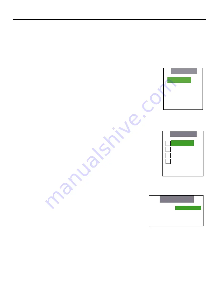
Input Position

Indicates selection has been made for the Input Position selection menu.

These settings are stored separately for each input and each resolution for that input.

•  Press ENTER to shift the Image Position Left/Right with the LEFT and RIGHT arrows.

•  Press ENTER to shift the Image Position Up/Down with the LEFT and RIGHT or UP/ 


DOWN arrows.

•  Press ENTER to adjust the Image Position Width with the LEFT and RIGHT arrows.

•  Press ENTER to adjust the Image Position Height with the LEFT and RIGHT or UP/   


DOWN arrows.

•  Press ENTER to allow shifting the Image Position Overscan percentage with the  

    LEFT and RIGHT arrows.

ISF Presets

Indicates selection has been made for the ISF Presets selection menu. These presets 

allow you to save the settings that are optimized for different viewing conditions. 

When you select a preset, all the picture settings will be reset. Any settings you have 

made  but  not  saved  will  be  lost. There  are  two  (ISF  Day  and  ISF  Night)  custom 

presets that you may use to save picture settings.

•  Press ENTER to select the ISF Night calibration settings.

•  Press ENTER to select the ISF Day calibration settings.

•  Press ENTER to select the Custom 1 calibration settings, or scroll RIGHT and  


press ENTER to save settings you have made.

•  Press ENTER to select the Custom 2 calibration settings, or scroll RIGHT and  


press ENTER to save settings you have made.

•  Press ENTER to force the Presets back to their Factory Default settings.

Information

Indicates selection has been made for the Information selection menu

•  Indicates the unit Serial Number on the front panel display.

•  Indicates the Hardware Version number on the front panel display.

•  Indicates the Firmware Version number on the front panel display.

•  Indicates the Firmware Version build date on the front panel display.

This information will help your service technician if there is a problem with your system.


Input Position

Left/Right

Up/Down
Width
Height
Overscan

       ISF Presets

     ISF Night

     ISF Day
     Custom 1   Save
     Custom 2   Save
      

     Factory Default

X

���������������

�����������

����������
�����������������

��������������������������
����������������������������������

Summary of Contents for PlasmaWall PL-43DHD

Page 1: ...OWNER S OPERATING MANUAL PL 43DHD PL 50DHD Flat Panel Display Monitor with TM and Digital High Definition Controller with Vivix II Technology ...

Page 2: ... Controller Description 11 Front Panel 11 Rear Panel 12 DHD Controller Remote Control 13 DHD Controller Connection Examples 14 Overall Functional Description 15 Quick Setup Guide 16 Menu Description and Navigation 17 Aspect Ratios 21 RS 232C Communications and Commands 22 RS 232C Commands 23 Dimensions 25 PL 43DHD 25 PL 50DHD 26 Specifications 27 Plasma Service Remote Control To be used by Authori...

Page 3: ...768 PL 50DHD HDTV resolution with 16 9 aspect ratio Designed for custom automation control with RS 232C and IR interfaces Accepts all DTV formats Multiple aspect ratio control Less than 4 1 2 inches thin Digital 480P 720P 1080i input via DVI w HDCP Advanced DHD Digital High Definition Video Controller Processor 2 Features and Benefits Due to the design of all plasma glass panels made by every manu...

Page 4: ...THIS UNIT TO RAIN OR MOISTURE ALSO DO NOT USE THIS UNIT S POLARIZED PLUG WITH AN EXTENSION CORD RECEPTACLE OR OTHER OUTLETS UNLESSTHE PRONGS CAN BE FULLYINSERTED REFRAIN FROM OPENINGTHE CABINET AS THERE ARE HIGH VOLTAGE COMPONENTS INSIDE REFER SERVICING TO QUALIFIED SERVICE PERSONNEL POUR EVITER UN FEU OU UN RISQUE D ELECTROCUTION NE PAS EXPOSER CET ENSEMBLE A LA PLUIE OU A L HUMIDITE DE MEME NE P...

Page 5: ...el D interférence du Canada 4 WARNING SAFETY TIPS Please read and follow the safety precautions listed below to ensure the equipment is free from damage and to ensure that no injury will occur as a result of improper use Do not insert any object especially metal or liquids into the Plasma display Do not place any objects containing water or any other liquid on top of the Plasma display Do not plac...

Page 6: ...ition Runco will provide new or rebuilt replacement parts for the parts that fail due to defects in materials or workmanship for a period of one 1 year from the effective date of delivery to the end user Such replacement parts are then subsequently warranted for the remaining portion if any of the original warranty period WHAT IS NOT COVERED UNDER THE TERMS OF THIS LIMITED WARRANTY Image burn in o...

Page 7: ...ou may also have other rights that vary from state to state EFFECTIVE WARRANTY DATE This warranty begins on the effective date of delivery to the end user For your convenience keep the original bill of sale as evidence of the purchase date IMPORTANT WARRANTY REGISTRATION Please fill out and mail your warranty registration card It is imperative that Runco knows how to reach you promptly if we shoul...

Page 8: ... as well as standard analog inputs 1 Install the Plasma display This could be either table mount or wall mount configurations 2 Connect the video interconnections between the output of any media source such as DVD players or satellite receivers or a DTV or computer source and the input of the plasma display 3 Plug in AC power to the Plasma display and turn the plasma on 4 Select the desired source...

Page 9: ...NALOG RGB IN INPUT1 mini D sub 15 pin RGB input from the DHD 5 ANALOG RGB OUT INPUT1 mini D sub 15 pin Use the ANALOG RGB OUT INPUT1 terminal to output the video signal to an external monitor or other component NOTE the video signal will not be output from the ANALOG RGB OUT INPUT1 terminal when the main power of this display is off or in standby mode 6 AUDIO INPUT1 Stereo mini jack Use to obtain ...

Page 10: ...PUT Stereo mini jack Used to output the audio of the selected source component connected to the main unit to an AV amplifier or similar component output can be set to variable or fixed 10 MAIN POWER switch Used to switch the main power or the main unit on and off 11 AC IN A power cable is furnished with the main unit Connect one end of the power cable to this connector and the other end to a stand...

Page 11: ...r flashes green once every one second when the AUTO POWER OFF function is operating 2 STANDBY Indicator This indicator is red during standby mode The flashing pattern is also used to indicate error messages 3 Display Stand Optional accessory for tabletop mount 4 Remote Control Sensor Receives the IR infra red commands from the remote control 10 1 3 4 2 ...

Page 12: ...direct select inputs or move the menu cursor Left in the On Screen Display When no menu is present on screen the LEFT button will toggle you through the different sources in the order of HD Pass Thru 2 HD Pass Thru 1 DVI 2 DVI 1 HD RGB2 HD RGB1 Component SD S Video 2 S Video 1 Composite 7 ENTER BUTTON When an item is highlighted on the On Screen Display the ENTER button will select the item 8 DOWN...

Page 13: ...DCP compliant 4 DVI 2 Digital DVI input 2 HDCP compliant 5 HD 1 Analog BNC connectors High Definition input 1 accepts RGB HV or YPrPb 480p 720p 480i 576i or 1080i 6 HD 2 Analog BNC connectors High Definition input 1 accepts RGB HV or YPrPb 480p 720p 480i 576i or 1080i 7 COMPONENT INPUT RCA connectors Standard Definition 480i 576i Component YPrPb input This is the input for component video from sou...

Page 14: ...Pass Thru 1 HD Pass Thru 2 5 LIGHT BUTTON Press this to illuminate the buttons 6 MENU BUTTON Pressing this button will access the OSD On Screen Display controls Press this button during the display of the sub menu to return to the previous menu or exit the OSD menus 7 VIDEO BUTTON Press this button to select VIDEO composite video as the source 8 COMP BUTTON Press this button to select Component SD...

Page 15: ...e quality Many sources have outputs that are limited to Composite video such as some VCR s and camcorders Others such as Laser Disc players actually produce slightly better results when using Composite video While the DHD Controller has an excellent decoder for Composite video it is recommended that Composite video be used only if necessary S VIDEO INPUT S Video is an improved video input over com...

Page 16: ...n ISF The ISF has developed carefully crafted industry recognized standards for optimal video performance and has implemented a training program for technicians and installers to use these standards to obtain optimal picture quality from Runco video display devices Accordingly Runco recommends that setup and calibration be performed by an ISF certified installation technician All signal types requ...

Page 17: ...ess Menu highlight an empty space below Information Press Enter Right Right Left Left Enter Note The system must be setup first by using S Video or Component 480i RCA input preferably Component 480i first 3 Select Component SD from the DHD controller 4 From the DHD controller press Menu button to call up the DHD OSD Use the Up or Down arrow button to select Calibration and press Enter 5 From the C...

Page 18: ...1 input Press ENTER to select the DVI 2 input Press ENTER to select the HD Pass Thru 1 input Press ENTER to select the HD Pass Thru 2 input If pass through is selected note that no on screen menus will be displayed since the signal is simply being looped directly through the analog output When pass through is the selected source pressing MENU will not automatically select the last selected input b...

Page 19: ... settings are stored separately for each input To access the picture quality adjustments press MENU and over the cursor down to Picture indicated by the green highlight and press ENTER The picture quality sub menu will then appear To make an adjustment to a particular function highlight the function with the up or down arrow buttons and press ENTER Once the function is on screen i e brightness pre...

Page 20: ...image To set COLOR properly look at the color bar pattern through a blue filter or mute the red and green outputs Adjust COLOR until the outer two tall color bars match labeled as white and blue to the outer short color bars see color bar drawing below BRIGHTNESS adjusts the black level of the image To adjust this properly adjust BRIGHTNESS until the below black bar JUST disappears but the above b...

Page 21: ...and RIGHT arrows ISF Presets Indicates selection has been made for the ISF Presets selection menu These presets allow you to save the settings that are optimized for different viewing conditions When you select a preset all the picture settings will be reset Any settings you have made but not saved will be lost There are two ISF Day and ISF Night custom presets that you may use to save picture set...

Page 22: ... with 16 9 DVD s LETTERBOX The image in the Letterbox mode will be stretched vertically and the top and bottom portion blanked off This ratio is best suited for DVD non anamorphic DVDs and LaserDisc movies 4 units wide 3 units tall STANDARD 4 x 3 The input signal will be scaled to fit in the center of the 16 9 sceen VIRTUALWDE A 4 3 image that is transformed into a 16x9 image to allow the user to ...

Page 23: ...g format command command value command etc i e COMPOSITE BRIGHTNESS 100 ANAMORPHIC CR NOTE In between commands a comma or space may be used NOTE A carriage return must be used after each command or string Other notes For command strings a maximum of 255 characters can be used in a single string PARAMETER min max refers to a function s minimum and maximum value range Inputting values above or below...

Page 24: ...ut horizontal position offset for current input and resolution IVPOS 100 100 YES Sets a value for input vertical position offset for current input and resolution IWIDTH 100 100 YES Sets the value for input width adjustment for current input and resolution IHEIGHT 100 100 YES Sets the value for input height adjustment for current input and resolution OVERSCAN 0 10 YES Sets the overscan value in for...

Page 25: ...NA NA Returns overscan percentage OVPOS NA NA Returns output vertical position value BRIGHTNESS NA NA Returns brightness setting value TINT NA NA Returns tint setting value PRESET NA NA Returns preset ISF day or night POWER NA NA Returns power status ASPECTIN NA NA Returns the input source aspect SWVER NA NA Returns software version number IWIDTH NA NA Returns input horizontal width value PHASE NA...

Page 26: ...25 DIMENSIONS PL 43DHD Plasma ...

Page 27: ...26 PL 50DHD Plasma ...

Page 28: ...ory only 100 120 VAC 50 60 Hz 220V AC Preset at the factory only Power Consumption 380W 480W Operating Environments 32 104 F 0 40 C 20 80 Humidity non condensing 32 104 F 0 40 C 20 80 Humidity non condensing Dimensions Width 43 3 8 in 1102 mm Depth 4 in 101 60 mm Height 26 3 4 in 679 40 mm Weight 80 lbs 36 3 kg Width 49 1 4 in 1251 mm Depth 4 3 32 in 104 mm Height 30 1 8 in 765 20 mm Weight 96 lbs...

Page 29: ...nt panel controls Screen Trigger Masking Outputs 3 12V DC 1 8A Bandwidth 180 Mega Samples Second MSPS Power Requirements 100 240V AC auto sensing 50 60 Hz 160W Operating Environments 41 95 F 5 35 C 0 90 Humidity non condensing Dimensions Width 17 1 2 in 444 50 mm Depth 4 3 8 in 111 13 mm Height 26 3 4 in 679 40 mm Weight 80 lbs 36 3 kg Included Accessories Rack mounting brackets Regulatory Approva...

Page 30: ...ess to cycle the monitor between on and standby D PC HDTV 1 Selects the 15 pin D sub input for computer type VESA signals or HDTV signals E HDTV 2 Selects the computer DVI input F INFO While video is being displayed this will display timing information about the selected signal G SDTV 1 Selects the first standard definition input either S Video or Composite video based on the toggle button H SDTV ...

Page 31: ...RUMA 010900 11 2 04 v2 1 Runco International Union City CA 94587 Ph 510 324 7777 Fax 510 324 9300 www runco com ...

Reviews: