Runco DTV-1101 Owner'S Operating Manual Download Page 32

Random Access Adjustment Mode

6-12

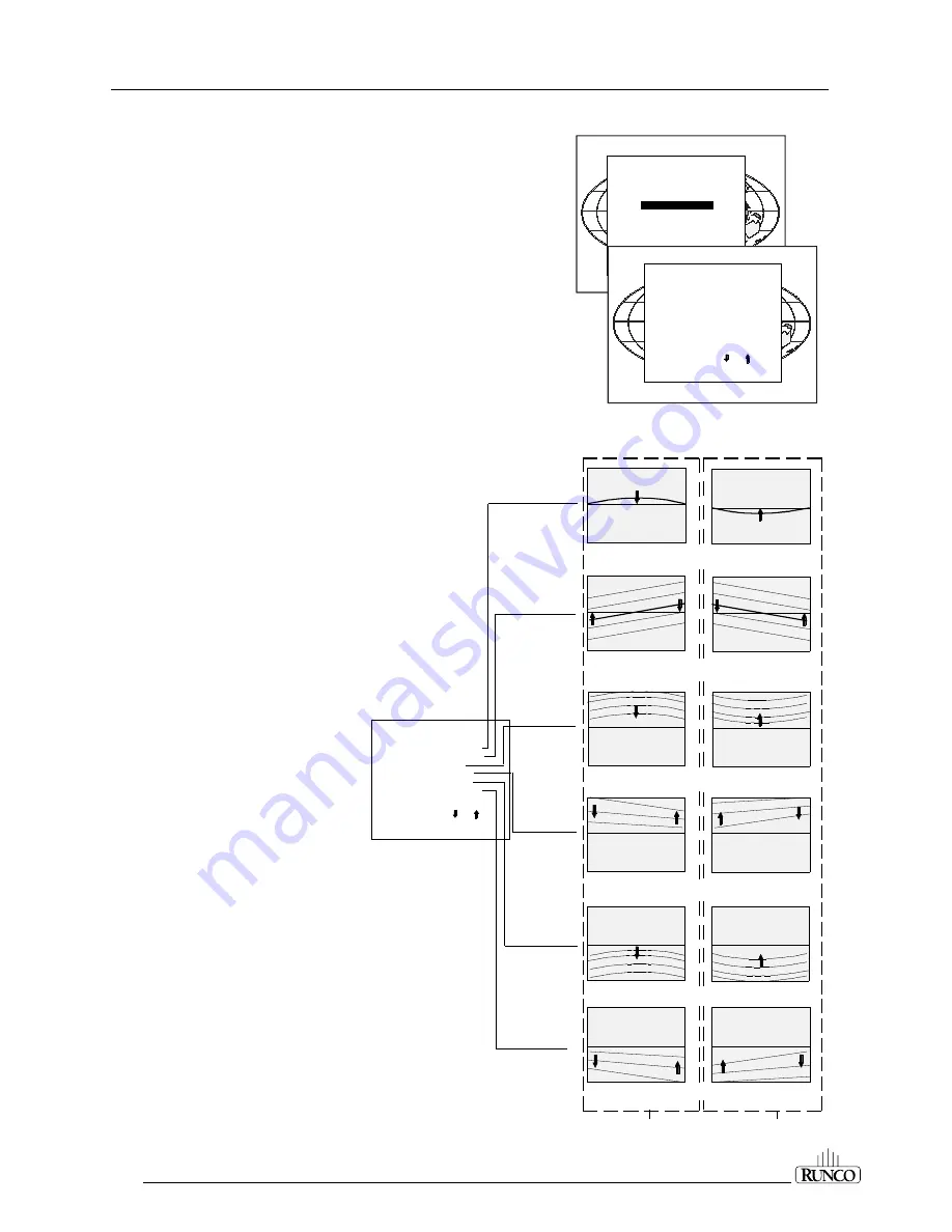
Top-Bottom (North-South) Adjustments

Top-Bottom and center adjustments affect only the horizontal lines of
the projected image. To start up the Top-Bottom and center correc-
tions, follow the next procedure:

Push the control disc up or down to highlight 

TOP-BOTTOM (N/S) on

the Geometry Menu and then press ENTER.

Only the green image is displayed while making top-botton adjust-
ments.  The red and blue images will automatically be corrected in the
same manner.  Convergence corrections are automatically disabled
for the duration of these adjustments.

The following adjustments can be executed:

- horizontal centerline bow
- horizontal centerline skew
- top bow
- top keystone
- bottom bow
- bottom keystone
- seagull correction

All adjustments are indicated on the screen with the function name, a
bar scale, and a number between 0 and 100.

Adjust the next alignments until the vertical lines are straight. To enter
an alignment, push the control disk up or down to highlight a function
and press ENTER to activate this function. Press EXIT to return.

TOP-BOTTOM

Select with       or

then <ENTER>

<EXIT> to return

H CENTERLINE BOW

H CENTERLINE SKEW

TOP BOW

TOP KEYSTONE

BOTTOM BOW

BOTTOM KEYSTONE

SEAGULL CORRECTION

Correct by pushing
the control disk down

Correct by pushing
the control disk up

Corrects for curvature of the horizontal lines in the
middle of the image.

Corrects the tilting of the horizontal lines in the middle
of the image.

Corrects the keystone geometry correction of the horizontal
lines on the upper side of the image.

Corrects the keystone geometry correction of the horizontal
lines on the lower side of the image.

Corrects for curvature of the horizontal lines on the upper
side of the image.

Corrects for curvature of the horizontal lines on the lower
side

Select with        or

then <ENTER>

<EXIT> to return.

GEOMETRY

H PHASE

RASTER SHIFT

LEFT-RIGHT (E-W)

LEFT SIDE CORRECTION

TOP-BOTTOM (N-S)

H SIZE

V LINEARITY

V SIZE

BLANKING

Select with        or

then <ENTER>

<EXIT> to return

TOP-BOTTOM (N-S)

H CENTERLINE BOW

H CENTERLINE SKEW

TOP KEYSTONE

TOP BOW

BOTTOM KEYSTONE

BOTTOM BOW

SEAGULL CORRECTION

Summary of Contents for DTV-1101

Page 1: ...OWNER S OPERATING MANUAL DTV Capable CRT Projector DTV 1101 THE WORLD S FINEST HOME THEA TER PRODUCTS R UN CO Super HDTV D T V V i d e o P r o j e c t o r...

Page 2: ......

Page 3: ...into the RCU 4 3 Input Selection 4 3 Analog Picture Controls 4 3 Controlling Chained Projectors 4 4 Start up of the Adjustment Mode 5 1 AdjustmentMode 5 1 Random Access Adjustment Mode 6 1 Starting Up...

Page 4: ...Deletion of All Blocks 7 3 Change Password 7 4 Change Language 7 4 Run Time 7 4 Set to Midposition 7 5 Undo Midposition 7 5 Convergence Mid 7 5 Undo Convergence Mid position 7 5 Dynamic Astigmatism s...

Page 5: ...RMANCE YOUR RUNCO PRODUCT IS CAPABLE OF PROVIDING WHEN INSTALLED AND CALIBRATED BY RUNCO AUTHORIZED PERSONNEL RIGHTS LIMITS AND EXCLUSIONS Runco limits its obligations under any implied warranties und...

Page 6: ......

Page 7: ...r or local power company 2 Thisproductisequippedwitha3 wiregroundingplug aplughaving a third grounding pin This plug will only fit into a grounding type power outlet This is a safety feature If you ar...

Page 8: ...efer servicing to qualified service personnel under the following conditions A When the power cord or plug is damaged or frayed B If liquid has been spilled into the equipment C If the product has bee...

Page 9: ...e connected to the projector Port 4 5 RGB S Input 5x BNC connector RGB Sinput allowsacharactergenerator microcomputer video camera etc having analog RGB output to be con nected to the projector Line i...

Page 10: ...selection Picture Controls use these buttons to obtain the desired level see also Controlling for each picture function TEXT when adjusting one of the image controls during a meeting the displayed ba...

Page 11: ...mains switch ON OFF Pressed ON Not pressed OFF The projector can start now in the operational mode image dis played or in the standby mode depending on the position of the power up dip switch on the...

Page 12: ...warm up period every 30 seconds a text box with the remaining time will be displayed on the screen for 2 seconds This text box will be displayed every time in another place Signal Input Connection to...

Page 13: ...D 4 GREEN 5 BLUE 6 ground RGBS 7 ground RGBS 8 Hor comp sync 9 Vert sync Connecting a RGB or Component Source to Port 4 5 RGBanaloginputterminals withseparateHandVsyncinputs with composite sync input...

Page 14: ...e can be connected to the projector via the Port 4 5 The projector detects automatically where the sync signal is located To select the component video input select component from the source selection...

Page 15: ...p side of the cover at the same time fig 1 Insert the new 9V battery type 6F22S or equivalent alkaline batteries are recommended in the lower compartment and connect the battery to the contact plate I...

Page 16: ...ess See Change Projector Address in Chapter 2 Service Mode Every projector requires an individual address between 0 and 255 which is set in the Service mode Only projectors with addresses between 0 an...

Page 17: ...indicated with the name of the control and an icon When an analog picture control is pressed a text box with bar scale andthefunctionnameofthecontrol e g brightness appearsonthe screen only if TEXT is...

Page 18: ...l Program the zero address into any RCU Press on the address key and key in the address 0 with the numeric keys on the RCU itself Once address 0 is pressed all projectors will be controlled together u...

Page 19: ...w adjustments SERVICE Service should be selected if the user intends to delete blocks change password select service adjustments or get set up information EYE Q This selection will access the EYE Q me...

Page 20: ......

Page 21: ...H PHASE RASTER SHIFT PICTURE TUNING GEOMETRY LEFT SIDE CORRECTIONS V CENTERLINE BOW SIDE BOW V CENTERLINE SKEW SEAGULL CORRECTION SIDE KEYSTONE LEFT KEYSTONE LEFT BOW LEFT RIGHT E W H CENTERLINE BOW...

Page 22: ...CONVERGENCE H SIZE V SIZE BLANKING LEFT BOTTOM RIGHT TOP V LINEARITY GREEN ONLY BLUE ON GREEN RED ON GREEN FOCUSING BLUE GREEN RED BLUE GREEN RED RED AND BLUE BLUE AND GREEN RED AND GREEN COLOR SELEC...

Page 23: ...set frequencies available Another 8 blocks are custom programmable Push the control disk up or down to highlight the desired crosshatch frequency Push the control disk to the left and to the right to...

Page 24: ...g Highlight Picture Tuning by pushing the control disk up or down and press ENTER The Picture Tuning Menu will be displayed Depending on the input source the Picture Tuning Menu will display different...

Page 25: ...nd press ENTER to toggle between NORMAL and RESTORATION Select Normal for all standard sources and all sources with a backporch 0 8 s for sources with noise and spikes in the signal Select Restoration...

Page 26: ...mbination of colors to display the projected image in that specific color To select a new color press ENTER The Color Selection Menu will appear again on the screen To terminate the color select proce...

Page 27: ...disk up or down to select bottom and press ENTER to continue to the bottom focusing Push the control disk up or down to adjust the bottom focusing Adjust until the lower part of the image is sharp ENT...

Page 28: ...nal sources Iftherastershiftiscorrectlyadjusted theHPhasetextboxisprojected in the middle of the raster At that moment the icon indicates the middle of the raster Adjust the H Phase control until the...

Page 29: ...t Adjustment EXIT returns to Random Access Adjustment Mode Menu Warning In order to ensure maximum CRT longevity and to avoid CRT damage do not shift the raster outside the phos phor area of the CRT T...

Page 30: ...th the function name a bar scale and a number between 0 and 100 Adjust the next align ments until the vertical lines are straight For side bow and side keystone look only to the right side of the imag...

Page 31: ...T to return All adjustments are indicated on the screen with the function name a bar scale and a number between 0 and 100 Adjust the next alignments until the vertical lines on the left side are strai...

Page 32: ...control disk up or down to highlight a function and press ENTER to activate this function Press EXIT to return TOP BOTTOM Select with or then ENTER EXIT to return H CENTERLINE BOW H CENTERLINE SKEW TO...

Page 33: ...ss ENTER ENTER will select horizontal size adjustment EXIT returns to Random Access Adjustment Mode Menu ADJUST returns to Operational Mode Adjust the horizontal size by the control disk to the right...

Page 34: ...the Geometry Menu and then press ENTER ENTER will select Vertical Size Adjustment EXIT returns to Random Access Adjustment Mode Menu ADJUST returns to Operational Mode Adjust the vertical size by pus...

Page 35: ...d pattern was selected theexternalsource willbedisplayed Adjustthenextblankingalignmentsuntiltheimageiscorrectlyframed or the unwanted information is blanked out To enter a blanking alignment push the...

Page 36: ...ENTER EXIT to return COARSE ADJUSTMENT RED ON GREEN BLUE ON GREEN FINE ADJUSTMENT GREEN ONLY RED ON GREEN BLUE ON GREEN Select with or then ENTER EXIT to return COARSE CONVERGENCE Select with or then...

Page 37: ...timizetheconvergenceoftheredandblueimageonthegreenimage Use the control disk to make horizontal or vertical convergence adjust ments in the selected zone and then press ENTER to move the box to anothe...

Page 38: ......

Page 39: ...ems are combined in two service menus To switch from the first to the second menu or vice versa push the control disk up or down to select More Select with or then ENTER EXIT to return SERVICE MODE ID...

Page 40: ...s ENTER ENTER will select the highlighted item To copy the settings of a closed block to the block you are working on active block use the control disk to select a block All existing settings will be...

Page 41: ...eleting If you are certain you wish to delete all blocks press ENTER to confirm Otherwise press EXIT to return Once ENTER is pressed all block headers and adjustment settings are permanently removed a...

Page 42: ...he language Run Time Highlight Run Time with the control disk and press ENTER to display the amount of time the projector has played since its first start up at the factory Note all projectors leave t...

Page 43: ...l this action select Undo Conver gence Mid by pushing the control disk up or down and press ENTER Undo Convergence Mid is displayed in the service mode menu in stead of Convergence Mid when this latte...

Page 44: ...ETE A BLOCK DELETE ALL BLOCKS CHANGE PASSWORD CHANGE LANGUAGE RUN TIME SET TO MIDPOSITION CONVERGENCE MID DYNAMIC ASTIGMATISM MORE DYNAMIC ASTIGMATISM ON SELECTED SOURCE RED GREEN BLUE ON GENLOCKED PA...

Page 45: ...a vertical way to prevent a CRT burn in To quit the CRT Run in Cycle option press EXIT Highlight CRT Run in Cycle with the control disk and press ENTER to start If a memory block adjusted on an inter...

Page 46: ...aining time indication Press another time EXIT to interrupt the warm up cycle Whenthewarm upoptionisOFF whenswitchingonthetheprojector it starts immediately with the projection of the selected source...

Page 47: ...emory bank the new screen sizewillbeassigned Thenewmemorybanknumberwillbedisplayed To ensure the new memory is saved perform any convergence function on the new memory This function is intended for cu...

Page 48: ......

Page 49: ...ncil or othersmallobject WARNING source not available The input is a valid input but the sourceisnotconnectedtotheinput terminals or the input source is switched off WARNING invalid key entry Whenawro...

Page 50: ......

Page 51: ...in 4 3 diagonal Throw Distance 1 38 x width widescreen 1 45 x width standard 4 3 Aspect Ratios 8 accessible from remote control including 1 33 standard 1 85 1 widescreen and Anamorphic Configuration F...

Page 52: ......

Page 53: ...2463 Tripaldi Way Hayward CA 94545 510 293 9154 Fax 510 293 0201 RUMA 003800 rev 10 00...

Reviews: