Runco CinemaWall CW-42i Owner'S Manual Download Page 65

Specifications

56

Specifications subject to change without notice.

Native Resolution: 


853 x 480

Screen Size:


42 in. (diagonal)

Screen Aspect Ratio:


16:9

Available Aspect Ratios:

  4:3, Letterbox


16:9 Anamorphic


Image Area (W x H):


36 1/3 in. x 20 7/16 in. 


 (921 mm) x (518 mm)

DTV Compatibility:


480p, 720p, 1080i

Contrast Ratio


1000:1

Data/Graphics Capability:

  640 x 400 to 1600 x 1200

Inputs: 


(2) Composite Video (1- BNC, 1- RCA)


(1) S-Video


(2) Component Video (1-BNC, 1-RCA)


(1) RGB (15-pin mini D-sub)   


(1) RGB via BNC


(1) DVI w/HDCP


(1) RS-232C


(4) 1/8” Stereo mini din jacks

Outputs:


(1) RGB (15-pin mini D-sub)


(1) Composite BNC

Power Requirements:


120V AC, 50/60 Hz

Power Consumption:


270W

Operating Environment:

  32°-104°F (0°-40°C), 


20-80% Humidity (non-condensing)
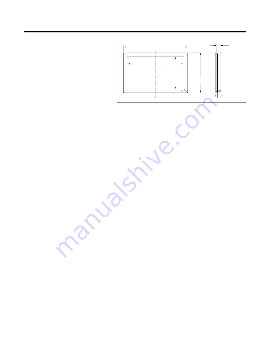
Dimensions: 


Width: 41 1/4 in. (1048 mm)      


Depth: 3 7/8 in. (98.43 mm)  


Height: 25 5/8 in. (651 mm) 


Weight: 67.5 lbs. (30.62 kg)

Regulatory Approvals:


FCC, CE, C-Tick

41.288 in (1049 mm)

36.308 in (922 mm)

20.680 in (525 mm)

25.660 in (652 mm)

2.914 in (74 mm)

2.066 in (52 mm)

Summary of Contents for CinemaWall CW-42i

Page 1: ...OWNER S MANUAL CW 42i Flat Panel Plasma Display Monitor...

Page 2: ...Configuration and Signal of the RGB 3 IN Connector DVI Connector 9 Basic Operations 10 Power 10 Volume 10 Mute 10 Display 10 Digital Zoom 10 Off Timer 11 Aspect Ratio Control 12 Wide Screen Operation...

Page 3: ...4 3 images without loss of picture quality The CW 42i has been carefully engineered for superb video performance at a very competitive price Its advanced design accommodates custom installation and e...

Page 4: ...recaution This plasma monitor is designed and manufactured to provide long trouble free service No maintenance other than cleaning is required Please see the section Plasma monitor cleaning procedure...

Page 5: ...a Never use solvents such as alcohol or thinner to clean these surfaces 2 Clean plasma ventilation areas with a vacuum cleaner with a soft brush nozzle attachment 3 To ensure proper ventilation cleani...

Page 6: ...tives Certaines d entre elles ne produisent pas de lumi re ou restent allum es Pour des raisons de s curit et pour viter d endommager l appareil lire attentivement les instructions suivantes Pour vite...

Page 7: ...iffon doux et sec Ne jamais utiliser de solvents dutypealcooloudiluantpourlenettoyagedecessurfaces 2 Nettoyer les prises d a ration du plasma en proc dant l aide d une brosse poils doux fix e un aspir...

Page 8: ...uct and therefore cannot be repaired under the terms of this Limited Warranty TO AVOID IMAGE BURN IN Please ensure that still images are left on your plasma display panel for no more than a few minute...

Page 9: ...ich you must be notified Repairs made under the terms of this Limited Warranty covering your Runco video product will be performed at the location of the product during usual working hours providing l...

Page 10: ...ure to use a stand or original mounting unit Wall mount unit stand etc For correct installation and mounting it is requiredtouseatrained RuncoAuthorizedDealer Failure to follow correct mounting proced...

Page 11: ...pend on the setting of BNC INPUT RGB COMP VIDEO1 VIDEO2 VIDEO3 HD DVD DTV RGB PC3 RGB PC2 RGB PC1 VIDEO1 VIDEO2 VIDEO3 HD1 DVD1 DTV1 RGB PC2 RGB PC1 HD2 DVD2 DTV2 5 LEFT and RIGHT Enlarges or reduces...

Page 12: ...e input is selectable Set which video image to distribute them from the audio menu screen E DVD1 HD1 Connect DVD s High Definition or Laser Discs etc here F RGB2 DVD2 HD2 RGB2 Connect an analog RGB si...

Page 13: ...display patterns EXIT Press this button to exit the OSM controls in the main menu Press this button during the display of the sub menu to return to the previous menu POINTER Press this button to displ...

Page 14: ...ation and Replacement Insert the 2 AAA batteries making sure to set them in with the proper polarity 1 Press and open the cover 2 Align the batteries according to the and indication inside the case 3...

Page 15: ...remote control sensor is exposed to direct sunlight or strong artificial light or if there is an obstacle between the sensor and the remote control Handling the remote control Do not drop or mishandl...

Page 16: ...B AUDIO 2 R MONO L AUDIO 3 R MONO L Cr Pr Y Cb Pb RGB 3 External Control IN OUT REMOTE VCR or Laser Disc Player VIDEO 1 3 DVD Player IBM VGA or Compatibles To Mini D Sub 15 pin connector on the plasma...

Page 17: ...the plasma monitor the following four display standards are supported using the Macintosh adapter 13 fixed mode 16 fixed mode 19 fixed mode 21 fixed mode The 13 fixed mode is recommended for your 42Wi...

Page 18: ...ectional DATA SDA Horizontal sync or Composite sync Vertical sync Data clock Pin No 1 2 3 4 5 6 7 8 9 10 11 12 13 14 15 1 2 3 4 5 6 7 8 9 10 11 12 13 14 15 16 20 19 18 17 21 22 23 24 RGB 3 Pin No 1 2...

Page 19: ...ld the VOLUME button on the remote control or the unit to decrease to the desired level MUTE To cancel the sound Press the MUTE button on the remote control to cancel the sound press again to restore...

Page 20: ...r has been set press the OFF TIMER button once 2 The remaining time is displayed then turns off after a few seconds 3 When five minutes remain the remaining time appears until it reaches zero OFF TIME...

Page 21: ...ressed in the horizontal direction squeezed images are expanded in the horizontal direction and displayed on the entire screen with correct linearity Normal images are expanded in the horizontal direc...

Page 22: ...f IBM Inc of the United States Note Do not allow the displayed in 4 3 mode for an extended period This can cause a phosphor burn in Wide Screen Operation with Computer Signals Switch to the wide scree...

Page 23: ...remote control to highlight the menu you wish to enter 3 Press the MENU ENTER button on the remote control to select a submenu or item PICTURE 1 2 EXIT CONTRAST BRIGHTNESS SHARPNESS COLOR TINT PICTURE...

Page 24: ...t values OFF Yes Main menu Sub menu Functions Default Reset AUDIO BASS Sets the bass Center Yes TREBLE Sets the treble Center Yes BALANCE Sets the left right balance Center Yes AUDIO INPUT1 3 Sets the...

Page 25: ...P OUT When set to ON the received signal will be looped out OFF Yes ID NUMBER Sets ID number for the display ALL Yes VIDEO WALL DIVIDER Creates a 2 2 or 3 3 video wall OFF Yes POSITION Sets the positi...

Page 26: ...mputer signal is connected Restoring the factory default settings Select DEFAULT under the PICTURE MODE settings Setting the picture mode according to the brightness of the room There are four picture...

Page 27: ...lasma display Example Setting HIGH Press the MENU ENTER button on the remote control to display the MAIN MENU on the screen then 1 Use the and buttons to select PICTURE then press the MENU ENTER butto...

Page 28: ...MA LOW TONE COLOR TUNE MID 3 AUTO SEL RETURN ADJ 4 Once the setting is completed Press the EXIT button to return to the main menu To delete the main menu press the EXIT button once more Information GA...

Page 29: ...adjustment CYAN Makes cyan s adjustment RESET Resets settings to the factory default value Use and buttons to select ON then press the MENU ENTER button Restoring the factory default settings Select...

Page 30: ...usting the Position Size Fine Picture Picture Adj The position of the image can be adjusted and flickering of the image can be corrected Example Adjusting the vertical position in the normal mode Pres...

Page 31: ...tores other settings to the factory defaults except for Auto Picture Option1 Settings Menu Setting the on screen menu This sets the position of the menu the display format horizontal or vertical etc E...

Page 32: ...INPUT SKIP ALL RESET NEXT PAGE CAN NOT ADJUST RGB RGB AUTO 1080B OFF OFF Setting a computer image to the correct RGB select screen With the computer image select the RGB Select mode for a moving imag...

Page 33: ...tching digital broadcasting 480P See page 41 for the details of the above settings Restoring the factory default settings Select ALL RESET under the OPTION1 menu Note that this also restores other set...

Page 34: ...n the main menu 1 2 then perform the following operations Press the MENU ENTER button on the remote control to display the MAIN MENU on the screen then 1 Use the and buttons to select OPTION2 then pre...

Page 35: ...CINEMA MODE ON Automatic discrimination of the image and projection in cinema mode OFF Cinema mode does not function Restoring the factory default settings Select ALL RESET under the OPTION1 menu Note...

Page 36: ...lines vertically every 3 minutes Perform Steps 1 3 of ORBITER then 4 Use the and buttons to select MANUAL then press the MENU ENTER button THE ORBITER screen appears 5 Adjust the items using the and...

Page 37: ...the minutes to 0M ON will be displayed SCREEN WIPER When this is set to ON a white vertical bar moves repeatedly from the left and of the screen to the right end at a constant speed Example Setting S...

Page 38: ...the following operations Press the MENU ENTER button on the remote control to display the MAIN MENU on the screen then 1 Use the and buttons to select OPTION2 then press the MENU ENTER button The OPTI...

Page 39: ...e Example Setting WEDNESDAY 22 05 Perform Steps 1 2 of TIMER then 3 Use the and buttons to select PRESENT TIME then press the MENU ENTER button The PRESENT TIME screen appears EXIT SEL RETURN PRESENT...

Page 40: ...the cursor with the DATE field that you wish to reset then press the CLEAR button To reset the data Align the cursor with the field ON OFF INPUT FUNCTION that you wish to reset then press the CLEAR bu...

Page 41: ...nu press the EXIT button once more Information CONTROL LOCK settings ON Disables the buttons on the front panel OFF Enables the buttons on the front panel Even when the CONTROL LOCK is set the POWER s...

Page 42: ...Select ALL RESET under the OPTION1 menu Note that this also restores other settings to the factory defaults ID number setting When using more than one of these displays this function sets ID numbers...

Page 43: ...rmation Restoring the factory default settings Select ALL RESET under the OPTION1 menu Note that this also restores other settings to the factory defaults DIVIDER Set the 2 2 or 3 3 video wall Example...

Page 44: ...5 seconds the current setting is set and the previous screen reappears 6 Once the setting is completed Press the EXIT button to return to the VIDEO WALL screen Information IMAGE ADJUST settings These...

Page 45: ...econds the monitor will be turned on PLE LINK Use this function to set a uniform brightness for each display Turn on the AUTO ID before the following operations Example Setting ON Perform Steps 1 2 of...

Page 46: ...Setting the menu mode This allows you to access full menu items When P ON DELAY or PLE LINK is ON this won t be turned OFF Example Setting ON Press the MENU ENTER button on the remote control to disp...

Page 47: ...formats Different countries use different formats for video signals Set to the color system used in your current country AUTO The color systems are automatically identified and the format is set accor...

Page 48: ...pment have been received When the lower order 4 bits is BH as in 3BH and 7BH this indicates that unsupported commands and data have been received Unit ID 1 and Unit ID 2 Unit ID 1 and unit ID 2 are nu...

Page 49: ...38 RESET 1FH 54H 00H 39 Audio Select Set DFH 70H 02H 40 BNC SELECT DFH 8CH 01H 41 RGB Select DFH 8BH 01H 42 HD Select DFH 8AH 01H 43 LANGUAGE Select DFH 5BH 01H 44 COLOR SYSTEM Select DFH 5CH 01H 45...

Page 50: ...SER PICTURE Gain Flag 01H DATA01 CONTRAST Gain Flag 07H DATA02 CONTRAST Gain CCH 52 FFH 01 00H 0 01H 01 14H 20 ACK 7FH 60H 80H 7FH 02H DATA00 DATA01 CKS DATA00 USER PICTURE Gain Flag 01H DATA01 CONTRA...

Page 51: ...CTURE MODE Select Function The external control equipment sets the picture mode of the plasma monitor Transmission Data DFH 80H 60H 0AH 01H DATA00 CKS DATA00 01H MEMORY 02H THEATER 03H NORMAL 04H RESE...

Page 52: ...H 17 NR MODE Set Function The external control equipment sets the NR Noise Reduction mode of the plasma monitor Transmission Data DFH 80H 60H C0H 01H DATA00 CKS DATA00 01H NR OFF 02H NR 1 03H NR 2 04H...

Page 53: ...ATA00 USER PICTURE Gain Flag 03H DATA01 V POSITION Gain Flag 01H 23 H POSITION Gain Data Function The external control equipment changes the H POSITION gain data of the plasma monitor Transmission Dat...

Page 54: ...a ratiooffrequency division of the plasma monitor Transmission Data DFH 80H 60H 7FH 03H DATA00 DATA01 DATA02 CKS DATA00 USER PICTURE Gain Flag 03H DATA01 CLOCK Gain Flag 04H DATA02 CLOCK Gain C0H 64 F...

Page 55: ...VEL 00H 0 0FH 15 33 CINEMA MODE Set Function The external control equipment switches on or off the CINEMA MODE of the plasma monitor Transmission Data DFH 80H 60H C1H 01H DATA00 CKS DATA00 CINEMA MODE...

Page 56: ...H 06M minutes FFH 12H hours and 45M minutes DATA03 SPEED 01H 1 05H 5 ACK 3FH 60H 80H C8H 00H CKS NOTE The WORKING TIME and the WAITING TIME can be set in units of 3 minutes Example 03H 9 minutes 1EH 1...

Page 57: ...the plasma monitor Transmission Data DFH 80H 60H 8AH 01H DATA00 CKS DATA00 01H 1035I 02H 1080A 03H 1080B ACK 7FH 60H 80H 8AH 01H DATA00 CKS DATA00 01H 1035I 02H 1080A 03H 1080B 43 LANGUAGE Select Fun...

Page 58: ...DATA06 00H No signal 01H to 80H RGB signal Identification number of PC mode 81H Video signal 3 58NTSC 82H 4 43NTSC 83H PAL 84H PAL M 85H PAL N 86H PAL60 87H SECAM 88H B W60 89H B W50 A0H HD DVD DTV s...

Page 59: ...ATA03 COLOR Gain E0H 32 COLOR Gain is from 22 EAH to FFH 01 22 16H only during video 00H 0 01H 01 20H 32 DATA04 TINT Gain E0H 32 TINT Gain is from 22 EAH to FFH 01 22 16H only during video 00H 0 01H 0...

Page 60: ...mal Bit 1 1 fixed backup Bit 2 TEMPERATURE 0 Abnormal 1 Normal Bit 3 1 fixed backup Bit 4 TEMPERATURE SENSOR 0 Abnormal 1 Normal Bit 5 1 fixed backup Bit 6 1 fixed backup Bit 7 1 fixed backup DATA01 F...

Page 61: ...tal NEG NEG NEG NEG NEG NEG NEG POS NEG POS POS POS POS POS POS POS NEG NEG POS POS NEG POS POS POS POS POS NEG POS POS POS POS POS POS POS POS POS Sync on G Sync on G Sync on G Sync on G NEG NEG C Sy...

Page 62: ...ter D Sub 15 pin to your computer s video port 7 Other screen modes ZOOM and STADIUM are available as well NOTE While the input signals comply with the resolution listed in the table above you may hav...

Page 63: ...l s buttons are pressed The front panel buttons of the main unit do not function No sound or picture is produced Picture appears but no sound is produced Poor picture with VIDEO signal input Poor pict...

Page 64: ...the monitor to a cooler location and wait for the monitor to cool for 60 minutes If the problem persists contact your Runco Authorized Dealer 2 In the following case power off the monitor immediately...

Page 65: ...omposite Video 1 BNC 1 RCA 1 S Video 2 Component Video 1 BNC 1 RCA 1 RGB 15 pin mini D sub 1 RGB via BNC 1 DVI w HDCP 1 RS 232C 4 1 8 Stereo mini din jacks Outputs 1 RGB 15 pin mini D sub 1 Composite...

Page 66: ...46...

Page 67: ...RUMA 010400 10 03 rev 1 Runco International 2900 Faber Street Union City CA 94587 ph 510 324 7777 fax 510 324 9300 www runco com...

Reviews: