Rugged Science Synapse v2000 User Manual Download Page 41

34

©

Rugged Science Synapse vX-Series 

 User Manual 

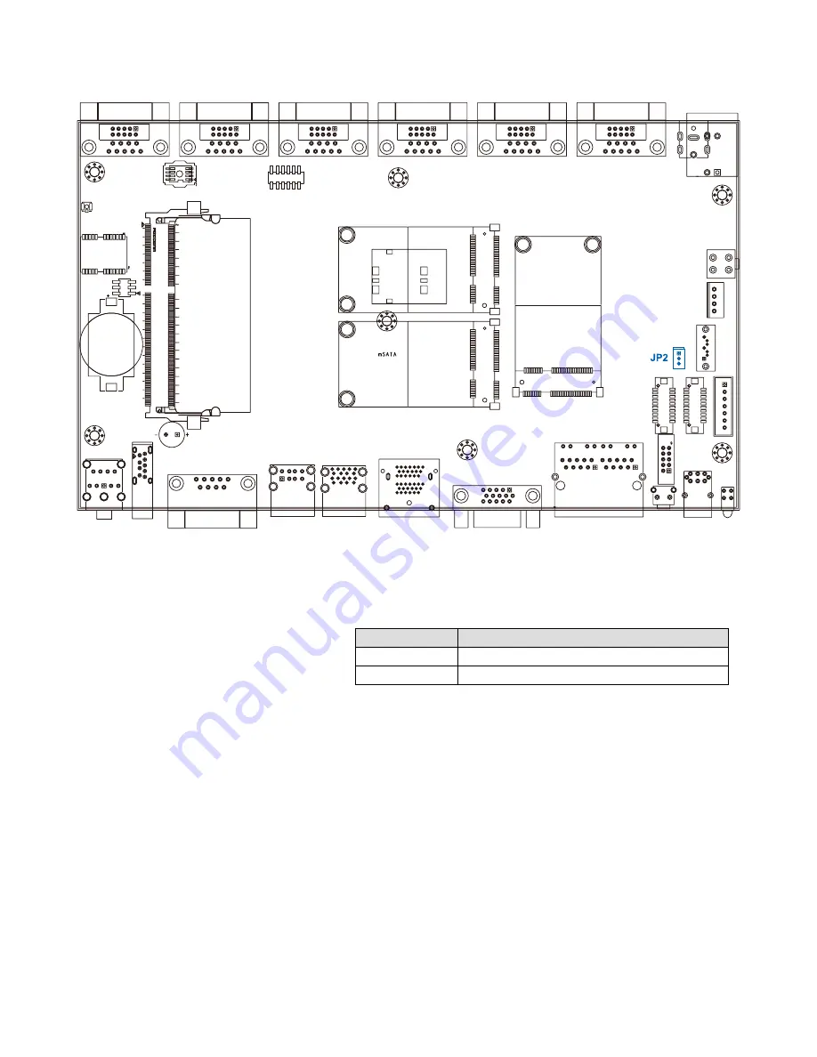
JP2 provides LVDS voltage selection function, closing 

Pin 1, 2 is for 3.3V LVDS power input; closing Pin 2, 3 is 

for 5V LVDS power input.

Setting

Description

1-2

+3.3V (Default)

2-3

+5V 

2.5.3 JP2 LVDS Backlight Power Selection

Summary of Contents for Synapse v2000

Page 1: ......

Page 2: ...ryland 21152 United States of America Toll Free 1 855 769 9747 Email sales ruggedscience com For further support information refer to the Technical Support and Professional Services appendix To commen...

Page 3: ...Record of Revision Version Date Page Description Remark V1 0 0 Jan 07 2014 All Preliminary Release V1 0 1 Jan 20 2014 p30 GPS Module V1 0 2 Feb 05 2014 p16 19 Rear Panel DC IN...

Page 4: ...adiate radio frequency energy and if not installed and used in accordance with the instruction manual may cause harmful interference to radio communications Operation of this equipment in a residentia...

Page 5: ...m Bay Trail E3815 Processor Part Number Description DDR3L8G Kingston DDR3L 1600 8G RAM DDR3L4G Kingston DDR3L 1600 4G RAM M340L W28M1 Rugged Science DDR3L 4GB 1333 1066MHz RAM Micron Chip Wide Tempera...

Page 6: ...ctors 15 2 3 Rear Side Exernal I O Connectors 16 2 3 1 Serial Ports COM1 and COM2 17 2 3 2 Serial Ports COM3 and COM4 17 2 3 3 Isolated Serial Port COM5 COM6 18 2 3 4 DC IN 9 28V 3 5 DC Jack or Termin...

Page 7: ...tion 44 4 2 5 Serial Port 4 Configuration 45 4 2 6 Serial Port 5 Configuration 46 4 2 7 Serial Port 6 Configuration 47 4 2 8 PPM Configuration 48 4 2 9 CPU Configuration 48 4 2 10 IDE Configuration 49...

Page 8: ...rom 25 C to 70 C for harsh environments With cutting edge graphics and computing technologies Synapse vX series enable to present high quality resolution 3D display as low power consumption Design wit...

Page 9: ...t Terminal Block ATX 2 Pin Remote Power On Off Switch Optional BOM On Board Power Input for PPC Power Output On Board 12V Storage SATA HDD 1 SATA II Ports at 3 0Gb s mSATA 1 miniPCIe full size Support...

Page 10: ...ply Power Input DC IN 9 28V ATX 2 Pin Remote Power On Off Switch Optional BOM On Board Power Input for PPC Power Output On Board 12V Storage SATA HDD 1 SATA II Ports at 3 0Gb s mSATA 1 miniPCIe full s...

Page 11: ...ower Supply Power Input Terminal Block ATX 2 Pin Remote Power On Off Switch Optional BOM On Board Power Input for PPC Power Output On Board 12V Storage SATA HDD 1 SATA II Ports at 3 0Gb s mSATA 1 mini...

Page 12: ...il I Family processors E3845 and E3815 are selected in Synapse vX series standard models and the rest is available upon project base Processor No Core Count CPU Freq GHz Gfx Freq MHz Nominal Turbo TDP...

Page 13: ...Product Introduction Rugged Science Synapse vX Series User Manual 1 4 Mechanical Dimension Figure 1 1 Synapse v2200 141 5 6 48 1 9 141 5 6 124 4 9 86 3 4 71 2 8 141 5 6 257 10 1 257 10 1 257 10 1 48 1...

Page 14: ...7 Getting to Know Your Synapse vX Figure 1 2 Synapse v2100 141 5 6 48 1 9 141 5 6 124 4 9 86 3 4 71 2 8 141 5 6 257 10 1 257 10 1 257 10 1 48 1 9...

Page 15: ...8 Rugged Science Synapse vX Series User Manual Figure 1 3 Synapse v2000 141 5 6 48 1 9 141 5 6 124 4 9 86 3 4 71 2 8 141 5 6 257 10 1 257 10 1 257 10 1 48 1 9...

Page 16: ...which contains Rugged Science Drivers Utilities DVD Wall mounting bracket M4 screws for wall mounting bracket 2 pin pluggable terminal block Synapse v2200 and Synapse v2000 1 2 4 2 On Synapse vX serie...

Page 17: ...in OS or just simply press the power button In case of system halts you can press and hold the power button for 4 seconds to compulsorily shut down the system Please note that a 4 seconds interval is...

Page 18: ...itable RJ 45 cable you can connect Synapse vX series system to a computer or to any other piece of equipment that has an Ethernet connection for example a hub or a switch Moreover both of them have Wa...

Page 19: ...m corner will flash on and off when Ethernet packets are being transmitted or received Location 10 Mbps 100 Mbps 1000 Mbps Right Bottom LED off Solid Green Solid Orange Left Bottom LED Flash Yellow Fl...

Page 20: ...ut mode supports up to 2560x1600 resolutions The HDMI mode is automatically selected according to the display device connected 2 2 7 Triple USB 3 0 Ports The Synapse vX series comes with 3 USB 3 0 hos...

Page 21: ...nables you to connect or disconnect a device whenever you want without turning off the system The hosts can be used for an external flash disk or hard drive for storing large amounts of data You can a...

Page 22: ...on 1 GPIO 0 SIO_GPI70 2 GPIO 1 SIO_GPI71 3 GPIO 2 SIO_GPI72 4 GPIO 3 SIO_GPI73 5 GND GND 6 GPIO 4 SIO_GPI74 7 GPIO 5 SIO_GPI75 8 GPIO 6 SIO_GPI76 9 GPIO 7 SIO_GPI76 2 2 10 Audio Connectors The Synapse...

Page 23: ...16 Rugged Science Synapse vX Series User Manual 2 3 Rear Side Exernal I O Connectors Figure 2 3 1 Synapse v2200 Rear Panel Figure 2 3 2 Synapse v2100 Rear Panel Figure 2 3 3 Synapse v2000 Rear Panel...

Page 24: ...S 232 COM1 2 1 DCD 2 RXD 3 TXD 4 DTR 5 GND 6 DSR 7 RTS 8 CTS 9 RI 2 3 2 Serial Ports COM3 and COM4 COM3 and COM4 can be configured for RS 232 RS 422 or RS 485 with auto flow control communication Seri...

Page 25: ...RS 232 if you want to use RS 422 or RS 485 you can find the setting in BIOS BIOS Setting Function COM5 COM6 RS 232 RS 422 5 wire RS 422 9 wire RS 485 RS 485 w z auto flow control The pin assignments...

Page 26: ...Wire 2 1 DCD TXD TXD DATA 2 RXD TXD TXD DATA 3 TXD RXD RXD 4 DTR RXD RXD 5 GND GND GND GND 6 DSR RTS 7 RTS RTS 8 CTS CTS 9 RI CTS The Synapse vX series offers 9 to 28 VDC power input Synapse v2200 an...

Page 27: ...ynapse vX Series User Manual Figure 2 4 1 Internal Connectors and Jumpers 2 4 Main Board Expansion Connectors The figure below is the top view of the Synapse vX series main board It shows the location...

Page 28: ...21 Getting to Know Your Synapse vX The figure below is the bottom view of the Synapse vX series main board...

Page 29: ...eset button power LED indicator and power on off button The front and top panel already provides access to these functions The following table shows the pinouts for Miscellaneous port J1 Miscellaneous...

Page 30: ...A 3 PANEL_VDD 3 3V or 5V by JP2 jumper PANEL_VDD 3 3V or 5V by JP2 jumper 4 LA_ DATA0_P LB_ DATA0_P 5 LA_ DATA3_P LB_ DATA3_P 6 LA_ DATA0_N LB_ DATA0_N 7 LA_ DATA3_N LB_ DATA3_N 8 PANEL_VDD 3 3V or 5V...

Page 31: ...No Definition CN24 Channel A CN25 Channel 18 PANEL_BACKLIGHT 12V PANEL_BACKLIGHT 12V 19 LA_ DATA2_N LB_ DATA2_N 20 GND GND The LCD inverter is connected to J2 via a JST 7 pin 2 5mm connector to provi...

Page 32: ...thin and short cables while application need larger storage capacity Pin No Definition 1 GND 2 TXP 3 TXN 4 GND 5 RXN 6 RXP 7 GND The Synapse vX series is equipped with one SATA power connector It supp...

Page 33: ...socket is being pulled up to logic 1 When a Mini PCI E device is inserted its pin 43 forces the respective pin on the socket to ground or logic 0 CN23 mSATA Connector Pin Out Pin No Signal Name Pin N...

Page 34: ...3Vaux 42 NC 23 PERn0 24 3 3Vaux 39 3 3Vaux 40 GND 21 GND 22 PERST 37 GND 38 USB_D 19 NC 20 NC 35 GND 36 USB_D 17 NC 18 GND Mechanical Key 15 GND 16 UIM_VPP 7 CLKREQ 8 UIM_PWR 13 REFCLK 14 UIM_RST 5 N...

Page 35: ...GND 16 NC 7 CLKREQ 8 NC 13 REFCLK 14 NC 5 NC 6 1 5V 11 REFCLK 12 NC 3 NC 4 GND 9 GND 10 NC 1 WAKE 2 3 3Vaux These pin headers can be used as a backup for the The Synapse vX series offers 8 programmab...

Page 36: ...m battery It is Equipped with Panasonic BR2032 190mAh lithium battery It is recommended that you not replace the lithium battery on your own If the battery needs to be changed please contact the Rugge...

Page 37: ...napse vX Series User Manual 2 4 8 GPS Module The Synapse vX series offers a u blox NEO 7 GPS GNSS modules can upgrade to NEO 8 and 2 0mm diameter I PEX antenna connector with 3 3 voltage power Antenna...

Page 38: ...lication by setting jumpers A jumper is a metal bridge used to close an electric circuit It consists of two metal pins and a small metal clip often protected by a plastic cover that slides over the pi...

Page 39: ...32 Rugged Science Synapse vX Series User Manual 2 5 1 JP1 A CMOS Clear Jumper Setting Setting Description 1 3 Normal Default 3 5 Clear CMOS...

Page 40: ...33 Getting to Know Your Synapse vX 2 5 2 JP1 B ME Clear Jumper Setting Setting Description 2 4 Normal Default 4 6 Clear ME...

Page 41: ...es User Manual JP2 provides LVDS voltage selection function closing Pin 1 2 is for 3 3V LVDS power input closing Pin 2 3 is for 5V LVDS power input Setting Description 1 2 3 3V Default 2 3 5V 2 5 3 JP...

Page 42: ...DIMM Modules 3 Remove the Pet Door and you can see a DDR3 SODIMM socket exposed Step2 Put the Synapse vX series upside down on a flat surface You can see the Pet Door exposed Use a Philips screwdriver...

Page 43: ...the socket snap into the latching position of SODIMM module Tile the SODIMM module and insert it to the SODIMM socket Step3 Remove the Pet Door and you can see a DDR3 SODIMM socket exposed Step2 Put t...

Page 44: ...own to make it contact with thermal pad Use a Philips screwdriver to fix the HDD with M3 screws Please note that the HDD must be placed in the right direction as below Step3 Pull out the SATA cable in...

Page 45: ...38 System Setup Rugged Science Synapse vX Series User Manual 3 3 Mount Your Synapse vX Installation Method 1...

Page 46: ...39 System Setup Installation Method 2...

Page 47: ...Flash The SPI Flash contains the BIOS Setup program POST the PCI auto configuration utility LAN EEPROM information and Serial port support The BIOS setup program is accessed by pressing the Del key a...

Page 48: ...ime Date Press TAB key to switch sub items of value Then press key or key number key for modify value In this page you could make sure you CPU type and DRAM type that you are install into this system...

Page 49: ...p state Select sleep state while SUSPEND button pressed 4 2 2 Serial Port 1 Configuration Figure 4 2 2 Serial Port 2 Setup screen Serial Port Enable or Disable Serial port Device Setting Current IO ad...

Page 50: ...up screen Serial Port Enable or Disable Serial port Device Setting Current IO addresses and interrupts resource of Serial Port Change Settings Select another device setting Here have 6 options Auto IO...

Page 51: ...able Serial port Device Setting Current IO addresses and interrupts resource of Serial Port Change Settings Select another device setting Here have 6 options Auto IO 3F8h IRQ 4 IO 3F8h IRQ 3 4 5 6 7 8...

Page 52: ...e Setting Current IO addresses and interrupts resource of Serial Port Change Settings Select another device setting Here have 6 options Auto IO 3F8h IRQ 4 IO 3F8h IRQ 3 4 5 6 7 8 9 10 11 12 IO 2F8h IR...

Page 53: ...able Serial port Device Setting Current IO addresses and interrupts resource of Serial Port Change Settings Select another device setting Here have 6 options Auto IO 3F8h IRQ 4 IO 3F8h IRQ 3 4 5 6 7 8...

Page 54: ...e Setting Current IO addresses and interrupts resource of Serial Port Change Settings Select another device setting Here have 6 options Auto IO 3F8h IRQ 4 IO 3F8h IRQ 3 4 5 6 7 8 9 10 11 12 IO 2F8h IR...

Page 55: ...puting setup screen EIST Enables or Disables Intel Speed function once you enabled it you could use the Intel Turbo Boost software to monitor you CPU performance Please refer to CPU check list 4 2 9 C...

Page 56: ...rovided by Vanderpool Technology 4 2 10 IDE Configuration Figure 4 2 10 SATA Configuration setup screen Serial ATA SATA Enables or Disables integrate SATA controller for Storage device use SATA Mode S...

Page 57: ...igure 4 3 1 Network Setup screen Chipset North Bridge Intel IGD Configuration Primary Display Primary Display Select which Display module you would like to you on current system PCI System display fun...

Page 58: ...oss Setup screen Chipset South Bridge Restore AC Power Loss Power Off When plug in the power source system will keep on SB mode Power On When plug in the power source system will auto booting Last Sta...

Page 59: ...iver Rugged Science Synapse vX Series User Manual 4 4 Boot Function 4 4 1 Change Boot Configuration Figure 4 4 1 Boot Setup screen Boot option When you press Enter you can select which device you woul...

Page 60: ...5 1 Boot Setup screen Restore Default Use the function to restore all BIOS setting but not include administrator password and system RTC value Save as Use Default Uses can use this function to match t...

Page 61: ...not support RT version Windows Server 2012 GPIO WDT Function The GPIO WDT are using internal Super IO function However you must entry super I O configuration mode to set it The output port is set as...

Page 62: ...uper I O special data port update_value Base control for read Super I O register outportb Super I O special address port Register Index inportb Super I O special data port It will return a BYTE value...

Page 63: ...tchDog Off set_data 0x30 0x00 Reg 0x73 is WatchDog timer For WDT Timer out value WatchDog counter start set_data 0xF0 0x02 WatchDog counter start set_data 0xF0 0x00 Reg 0x72 is WatchDog time out value...

Reviews: