Rugged CCTV SCOUT III Instruction Manual Download Page 11

IR Dome Camera Instruction Manual 


10 

Attention:   

If the protocol setting of the dome is set to auto detection, the protocol of keyboard controller 
can be set arbitrarily. But its baud rate should be set identical with that of the dome device. 

4.6 Start testing 

  When all of the above settings are completed you can start testing the dome functionality 


Please refer to the next section for demonstration of menu operation and control of dome device.


4.7. Complete the test (Summary) 

1.


If you have achieved control of the dome device as described above, the system is basically 

normal. Please do not change the wiring or the applied settings to avoid unnecessary 
damage. 

2.


If  the  dome  does  not  respond  to  the  commands  or  only  partial  functionality  is  achieved, 

verify the wiring connection and communication settings. 

4.8 Operation commands 

Functional  number  range:  1

165,including  positional  preset  points  and  functional  preset 

points. 
Positional preset point range :1

50,64 

77 and 102

165 

Functional preset point range:51

63,78

101. 

The following command operated by controller: 

Set Home Position 

Function: The dome unit will auto return to No.1 preset position without receiving any 
controlling demand during set time with unmanned watch. 
The time interval for returning to Home (preset 1) can be set from 1-2-4-8-10 minutes by : 
Call No. 95 preset position to set 1 minute 
Call No. 96 preset position to set 2 minutes 
Call No. 97 preset position to set 4 minutes 
Call No. 98 preset position to set 8 minutes 
Call No. 99 preset position to set 10 minutes 
To disable the return to Home Position function press No.100 preset postion 

Setting Auto Pan scanning between two points: 

User only needs to maintain a certain manual scan speed for more than 3 seconds and call 
No.101 preset position to continue the auto pan scanning for certain area with specific speed 
and operate tilt action and real-time zoom. 


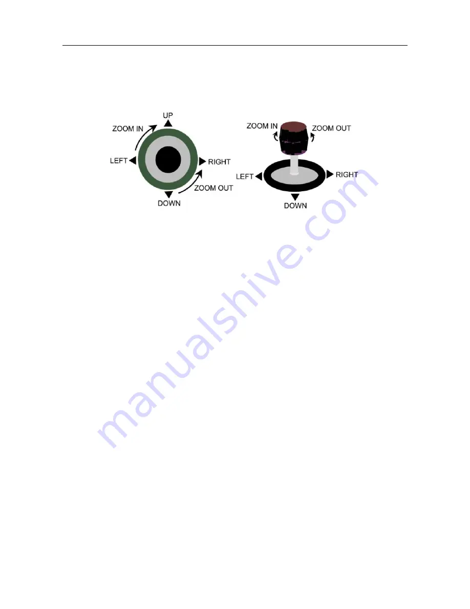
The direction (up, down, left and right)of 
the dome device can be controlled by 
using the keyboard controller, as 
indicated in the figure. 
Note: the working of dome device is 
normal.


Zooming of the camera can be controlled by 
zooming function Joystick or by using 
TELE(zoom in) and WIDE(zoom out) on the 
keyboard button. 
Note: The camera and dome device are 
normal 

Summary of Contents for SCOUT III

Page 1: ...Instruction Manual Please read this manual carefully before installation and use This manual is subject to change without notice SCOUT III Infrared PTZ CAMERA 1 866 301 2288...

Page 2: ...le damage to the product 4 Please DO NOT remove or disassemble any internal parts of the device to avoid mal operation and possibly void the warranty There are no serviceable parts inside the camera 5...

Page 3: ...nication settings 7 Chapter 4 Quick Start Operation Guide 9 4 1 Wiring Instruction 9 4 2 Setting protocol and baud rate 9 4 3 Camera installation 9 4 4 Connect the power to the dome 9 4 5 Joystick con...

Page 4: ...ng usage user should abide by all electrical safty standards and adhere to electric specifications for the operation of the dome Use only the power supply transformer specified by the manufacturer The...

Page 5: ...irs as a reference 4 Three user definable PTZ tour also called pattern with up to 2 minutes record duration for each tour User has the ability in real time to monitor and record the action of a manual...

Page 6: ...g with regular time 6 Resume operation function The idle time and motion option i e call preset position auto tracking PTZ tour can be set in advance with resume operation function The dome unit will...

Page 7: ...Day night switch function applicable to the camera module having the function of color and black white switch The function of color and black white switch will be achieved automatically 6 Menu operati...

Page 8: ...ystem 3 2 1 Setting the protocol and baud rate for each dome device Attention The protocol and baud rate of IR dome camera should comply with those of the controller which need to be restarted after r...

Page 9: ...N 1 2 3 4 5 6 7 8 Dome device range 0 255 Matching numbe rs 16 8 4 2 Dome device range 0 255 On Off status Baud rate 5th digit 6th digit 2400 OFF OFF 4800 OFF ON 9600 ON OFF 19200 ON ON Dip Switch 2 4...

Page 10: ...e may have different screws holes 4 4 Connect the power to the dome As soon as the power is turned ON the dome initiates a self test which includes a rotation of the dome on both axis and the camera w...

Page 11: ...The following command operated by controller Set Home Position Function The dome unit will auto return to No 1 preset position without receiving any controlling demand during set time with unmanned w...

Page 12: ...to enter number editing programming The default No is 1 Joystick left right to select the number to be edited and press OPEN to confirm Joystick left right to select number range from 0 9 Press OPEN t...

Page 13: ...ess OPEN to confirm your selection or press CLOSE to exit Name Move the joystick up down to select Name Move the joystick left right or press OPEN to confirm the selection and enter Name submenu Joyst...

Page 14: ...n done Name Display Move the joystick up down to select Name Display option Joystick left right to choose ON or OFF Press CLOSE to return to upper menu Coordinates Move the joystick up down to select...

Page 15: ...stick left right or press OPEN to confirm the selection and enter submenu Press OPEN or joystick left right Press CLOSE Press OPEN or joystick left right Press CLOSE Press OPEN or joystick left right...

Page 16: ...osition if this function is disabled Press CLOSE to exit and return to upper menu Speed Limit ON OFF Move the joystick up down to select Speed Limit Move the joystick left down to select ON OFF The do...

Page 17: ...using this function Restore Def Setting Move the joystick up down to select Restore Def Setting Move the joystick left right or press OPEN to confirm the selection User can resume all default data of...

Page 18: ...AF Sensitivity Joystick left right to select High Low Camera Exposure Move the joystick up down to select Camera Exposure Move the joystick left right or press OPEN to enter the submenu Press OPEN or...

Page 19: ...the joystick up down to select Number Joystick left right to select desired number Mask Edit Move the joystick up down to select Mask Edit Move the joystick left right or press OPEN to confirm and en...

Page 20: ...ect WB Mode Move the joystick left right to select Auto Manual Indoor Outdoor OnePush ATW R Gain Adjustable under WB Mode Manual B Gain Adjustable under WB Mode Manual Vertical Mirror Move the joystic...

Page 21: ...Z or _ Press OPEN to confirm and press CLOSE to exit and return to upper menu Program a Tour Move the joystick up down to select Program a Tour Move the joystick left right or press OPEN to confirm a...

Page 22: ...n Joystick left or right to select preset position and press OPEN to confirm Joystick left or right again to select numbers 0 9 Press OPEN to confirm the selection Press CLOSE to exit or return to upp...

Page 23: ...or press OPEN to confirm and enter the menu Delete a VectorScan Move the joystick up down to select Delete a VectorScan Move the joystick left right or press OPEN to confirm and enter the menu Press...

Page 24: ...eset 87 Call 87 Start VectorScan 5 Preset 88 Call 88 Start VectorScan 6 Preset 89 Call 89 Joystick between freeze and unfreeze video Preset 90 Call 90 Setup the Menus and Camera Preset 91 Call 91 Invo...

Page 25: ...scan 84 S Two point scan 200 S Intelligent Power off memory Support Home position One Cryogenic high temperature and thermostat system Support Fan circulation system Support Heat sink All metal alumin...

Page 26: ...r or image Interfered by exterior electronic signal noise or the camera is directed to the monitor screen Grounding the dome device or shut off the surrounding big electronic devices electric HF signa...

Page 27: ...control of dome device Overload or too long distance transmission Add driver Mostly happen in the connection Improper contact of control cable Check the circuit Slip ring is damaged Replace slip ring...

Page 28: ......

Reviews: