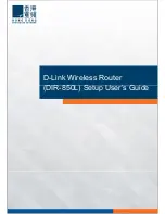
FIGURE 3 Typical AP high-density narrow-sector coverage
Mounting Instructions
Connecting And Sealing the RJ-45 Cables
Connect and seal the RJ-45 cable(s) using the M25 data
cable glands shown in the Figure below.
WARNING!
Do not use any PoE injector not tested and
approved by Ruckus Wireless to power the T310n Access
Point.
FIGURE 4 T310n LEDs and Ports
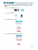
1. Feed the end of the cable through the sealing nut, rubber
O-ring, clamping ring assembly and cable gland base as
shown.
NOTE: Do not seat the clamping ring and rubber O-ring
into the gland body until the gland body has been
torqued to spec.
FIGURE 5 RJ-45 cable and cable gland assembly
2. Use a wide flat-blade screwdriver to remove the required
(PoE IN) blanking cap from the AP.
3. Connect the cable to the Ethernet port on the AP.
4. Tighten the cable gland base into the AP chassis to 7 N.m
or 62 in-lbs.
5. Wrap the clamping ring assembly around the rubber O-
ring. Make sure that the clamping ring assembly fully
encloses the rubber O-ring.
6. Seat the clamping ring assembly and rubber O-ring in the
cable gland base.
7. Hand-tighten the sealing nut.
Attaching the U-Joint Bracket to the Mounting
Bracket
1. Position the U-joint bracket on the mounting bracket.
NOTE: Mount the U-joint bracket in any direction on the
mounting bracket, preferably to allow AP azimuth
adjustments. Then the AP bracket allows AP elevation
adjustments.
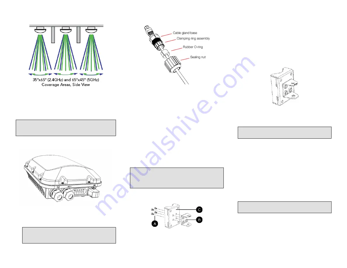
FIGURE 6 U-joint bracket attached horizontally to the mounting bracket
2. Use four 1/4-28 bolt and washer sets (A) to mount the U-
joint bracket (B) to the mounting bracket (C). Tighten the
bolts to 9.5 N.m (7 ft-lbs).
3. Continue with
Attaching the Mounting Bracket to a Flat
Surface
or
Attaching the Mounting Bracket to a Pole
.
Attaching the Mounting Bracket to a Flat Surface
1. Place the mounting bracket at the location on the flat
surface where you want to mount the AP. Use the holes
on the mounting bracket as a template to mark the
locations of the mounting holes.
FIGURE 7 Mounting bracket flat surface holes
2. Remove the mounting bracket from the flat surface.
3. Drill holes required for the mounting hardware.
NOTE: The hardware required for mounting to a wall
are not included in the mounting kit.
4. Attach the mounting bracket to the flat surface using the
mounting hardware.
5. Using the mounting hardware instructions, tighten the
hardware to secure the mounting bracket.
6. Continue with
Mounting the Linkage Bracket to the U-
Joint Bracket
.
Attaching the Mounting Bracket to a Pole
1. Insert the open end of one steel clamp into the upper two
slots on the mounting bracket.
2. Take the other steel clamp and insert it into the lower two
slots on the mounting bracket.
NOTE: The clamps can be daisy-chained together to
accommodate larger poles.
3. Use the clamps to attach the mounting bracket to the
pole. Tighten the clamps to 3 N.m or 27 in-lbs, or per
manufacturer’s specifications.
Copyright
®
2017 Ruckus Wireless, Inc.
Page 2 of 4
Published September 2017, Part Number 800-71623-001 Rev A