Ruckus Q710 LTE
Access Point
Quick Setup Guide
This Quick Setup Guide provides step-by-step instructions on
how to set up your Ruckus Q710 LTE Access Point (AP). After
completing the steps described in this guide, you will be able to
place Q710 at your site and provide LTE wireless network access
to users.
FIGURE 1 Ruckus Q710 LTE Access Point
Before You Begin
Before deploying Ruckus Wireless products, please check for the
latest information and release documentation at
http://support.ruckuswireless.com/documents
Software License and Limited Warranty are available at
http://support.ruckuswireless.com/warranty
Package Contents
Check the package contents as follows:
• Ruckus Q710 LTE Access Point
• Mounting bracket
• 4 Bracket screws (Phillips #2)
• 2 Wall Mounting screws (Phillips #2)
• 2 Wall Anchors
• US AC/DC Adapter
• This Quick Setup Guide
Mounting Instructions
Access Point (AP) can be mounted to a drop-ceiling T-bar or flat
surface.
Mounting on a Drop-Ceiling T-Bar
The factory-supplied mounting bracket allows you to attach the
AP to drop-ceiling T-bars.
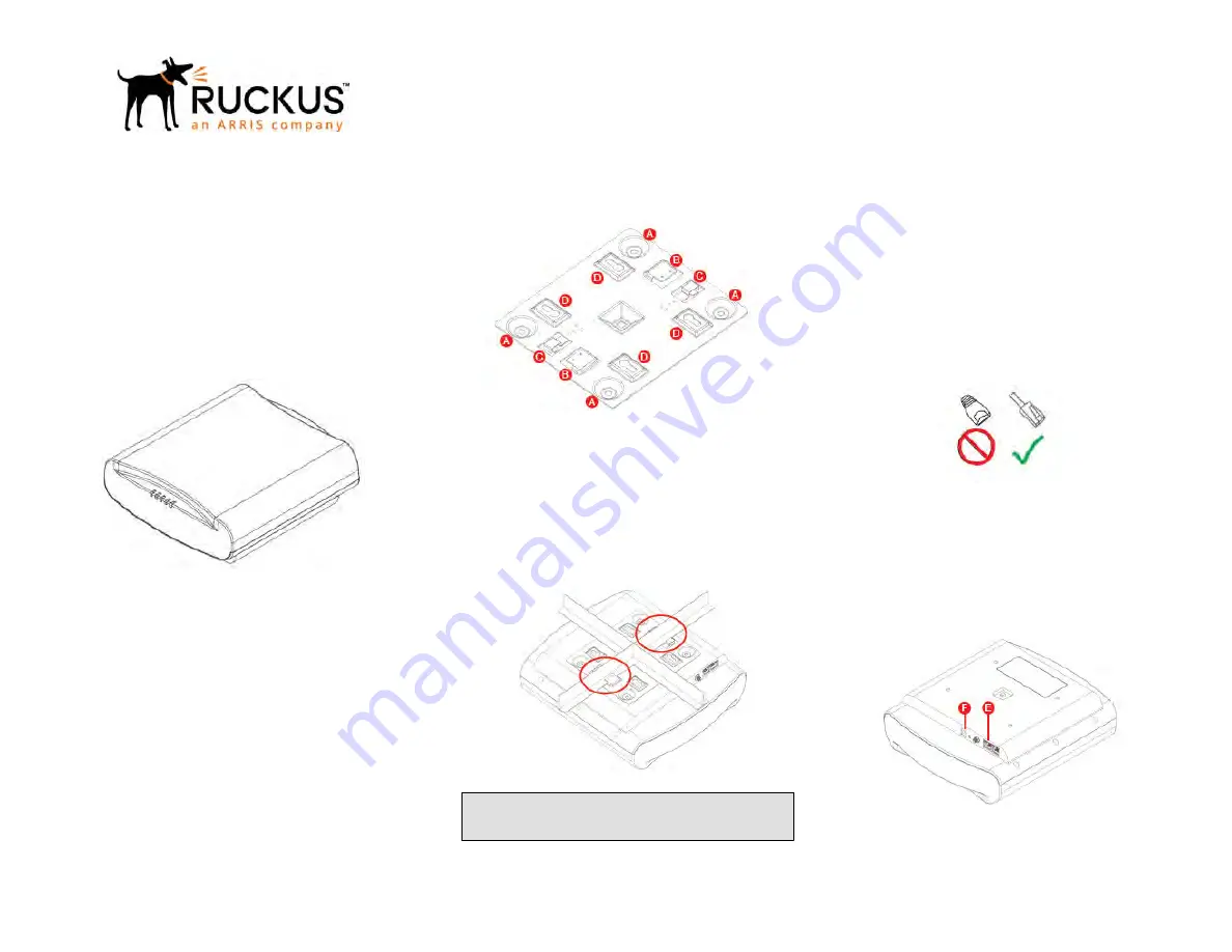
FIGURE 2 AP Mounting Bracket
1. If not attached already, attach the bracket to the AP at [A]
using the included Bracket screws.
2. Lift the AP with the bracket facing drop-ceiling and position
Studs [B] on the bracket slightly offset from either side of the
T-bar.
3. Gently turn the AP clockwise until the Studs slip over the T-
bar and both clasps [C] snap in place against the T-bar.
FIGURE 3 AP securely attached to T-bar
NOTE: In order to properly support its weight, make sure
that the AP is mounted at the intersection of two rails and
not along a single rail.
4. To un-mount the AP, simply press down on the two clasps [C]
and gently turn the AP counter-clockwise until it comes off.
Mounting on a Flat Surface
The factory-supplied mounting screws and plastic wall anchors
allow you to attach the AP to a wall or ceiling.
• Attach the bracket to the AP using included Bracket screws.
• Use the Wall Mounting template represented on the last page
of this Quick Setup Guide to mark the locations for two drill
holes on the mounting surface.
• Use a 4.75 mm (3/16") drill bit to drill holes approximately 25
mm (1") deep into the mounting surface.
• Insert factory-supplied anchors and mounting screws into the
mounting surface, leaving approximately 6 mm (1/4") of the
screw heads protruding for the AP bracket.
• Place the AP and bracket onto the mounting screws so that
screw heads enter the Keyholes [D] on the AP bracket and
gently push down.
Making the Connections
Be sure to use a Cat 5e or better Ethernet cable with non-booted
connectors (see Figure 4).
FIGURE 4 Non-booted Ethernet Connector
If using PoE, attach one of the Ethernet cable to an 802.3at Type
2-certified switch or PoE injector (sold separately). Attach the
other end of the Ethernet cable to the leftmost Ethernet port [E]
on the AP as shown in Figure 5. If using an AC/DC adapter,
connect it to the power port [F] in Figure 5 and to an electrical
outlet.
FIGURE 5 Port Locations
Checking the LED Lights
LED lights verify the installation of APs.
Once connected, the AP will power on and automatically connect
to the Ruckus Cloud over the Internet to configure itself. You will
Copyright
©
2018 ARRIS Enterprises LLC. All rights reserved.
Page 1 of
2
Published 9 July 2018, Part Number 800-71275-001 Rev C


