Ruck FFH 125 EC 10 Assembly And Operating Manual Download Page 9

English

5.  Transport and storage

6. Assembly

Transport and storage should only be performed by specialist personnel in accordance with the installation 

and operating manual and regulations in force.

The following points should be noted and followed:

• 

Check the delivery according to the delivery note to ensure it is complete and correct and check for 

any damage. Any missing quantities or damage incurred during transport should be confirmed by the 

carrier. No liability is accepted if this is not observed.

• 

The product weighs approx. 17 - 32 kg (depending on the product type in question).

• 

It should be transported with suitable lifting equipment in the original packaging or on the transport 

equipment indicated.

• 

If transported with a forklift it should be ensured that the product is resting with the basic profile or 

base frame completely on the forks or on a pallet and the product‘s centre of gravity is between the 

forks (see Fig. 4).

• 

The driver must be authorized to drive a forklift truck.

• 

Do not go beneath the suspended load. 

• 

Only lift and transport the machine by its base plate, never by the cover handle! 

• 

Avoid damage or deformation of the housing.

• 

The product must be stored in a dry area and protected from the weather in the original packaging. 

Open pallets should be covered with tarpaulins. Even weatherproof modules should be covered 

because their weather resistance is only guaranteed after complete installation.

• 

Storage temperature between  –10 °C and +40 °C. Avoid severe temperature fluctuations.

• 

If the product has been in storage for more than a year, check the smooth running of impellers and 

valves by hand.

Assembly work may only be performed by specialist personnel in accordance with the installation and 

operating manual and the regulations and standards in force.

The following points should be noted and followed:

• 

The product should only be installed on ceilings with the cover on the bottom (installation height: min 

1.8 m above the ground). Alternative installation positions are given in Section 6.1 „Permitted installa

-

tion positions“.

• 

Only install in dry rooms with no condensation.

• 

Installation accessories should be provided by the client.

• 

Only suitable installation aids, in accordance with regulations, should be used.

• 

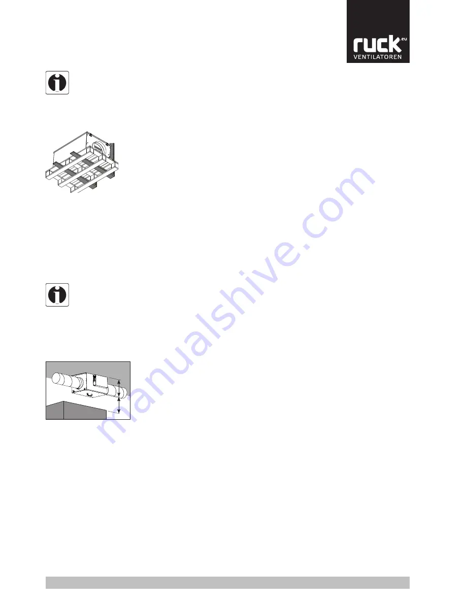
The installation should be easily accessible for maintenance and cleaning and should be easy to 

dismantle. Leave a space of at least the height of the unit + 5 cm from other units, shelves or cabinets 

to facilitate maintenance work such as changing the filter (see Fig. 5).

• 

The unit should only be installed with authorized and suitable fastening materials at all fastening 

points.

• 

It must be fastened with screws or threaded rods, minimum diameter 8 mm.

• 

The unit should only be installed on ceilings with adequate load-bearing capacity. Wall installations 

are only permitted in the positions shown in Section 6.1 „Permitted installation positions“.

• 

Do not distort the unit when installing.

• 

The unit should be suitably secured.

• 

No holes should be made in the housing, or any screws screwed into it.

• 

The duct system must not be supported on the housing.

• 

It is recommended that the duct system is attached with flexible connections in order to isolate any 

structure-borne noise.

• 

Make sure that the duct system cannot be closed.

• 

Make sure that the intake duct has direct access to the intake air.

• 

Warning: branches in the intake duct, to other fan units for example, may, if the dimensions are too 

small, lead to low pressure in the duct and therefore malfunction of the unit.

• 

The pressure loss in the duct system must not be more than the capacity of the unit! The pressure 

loss in the duct should not be more than 2/3 the unit‘s maximum pressure so that an adequate air 

output can still be achieved. This will prevent malfunction. 

• 

Pressure losses in the duct system are adversely affected by: the length of the duct system, small 

pipe or duct cross-section, elbows, additional filters, valves, etc.

Fig. 4:

Unit transported on a pallet with 

a forklift.

Fig. 5:

Minimum distance for 

maintenance work.

9

H

H+5 cm

00

137771

www.ruck.eu

Summary of Contents for FFH 125 EC 10

Page 1: ...Assembly and Operating Manual Compact Supply air unit English 00 137771 www ruck eu FFH 125 EC 10 FFH 150 EC 10 FFH 160 EC 10 FFH 200 EC 10 FFH 250 EC 10 FFH 315 EC 10 FFH EC...

Page 2: ...m the obligati on of own judgment and verification It must be remembered that our products are subject to a natural process of wear and aging This document as well as the data specifications and other...

Page 3: ...tions 10 6 2 Operating limits 10 7 Electrical connection 10 7 1 Overcurrent protection 11 7 2 Wiring diagrams 12 7 3 Connection EC extract fan 12 8 Commissioning 13 9 Operation 14 9 1 Control unit 14...

Page 4: ...ntended use Exclusively use ruck Ventilatoren in good technical order and condition Check the product for visible defects for example cracks in the housing or missing rivet screws and covers Only use...

Page 5: ...qualifications In this manual there are safety instructions before the steps whenever there is a danger of personal injury or damage to the equipment The measures described to avoid these hazards must...

Page 6: ...t not be changed or removed Make sure that all electrical connections are either used or covered Commission the product only if it is installed completely 2 5 3 During commissioning 2 5 4 During opera...

Page 7: ...letely from the electri city supply and make sure that it cannot be switched back on again Never clean the internal space with flowing water or a high pressure cleaner Do not use aggressive or easily...

Page 8: ...he right amount of ventilation for the requirements Data in detail Galvanized steel housing Removable aluminium cover Extractable fan unit Free running backwards curving impeller External rotor motor...

Page 9: ...on height min 1 8 m above the ground Alternative installation positions are given in Section 6 1 Permitted installa tion positions Only install in dry rooms with no condensation Installation accessori...

Page 10: ...Any cable inlets that are not used must be sealed so that it is airtight All cable inlets must have strain relief Create equipotential bonding between the unit and the duct system Check all protective...

Page 11: ...A Unit malfunction If there is a malfunction on the unit an error message appears on the display and at the same time switches a relay A closing and opening signal is available see wiring diagram Ele...

Page 12: ...ntakt free potential contact St rung Ger t unit fault 10 1112 XB3 1 2 3 X5 Freigabe Ger t unit enable Einspeisung Einspeisung 230V 1 N 50Hz Sicherung extern max 16A Fuse external max 16A Bedienger t r...

Page 13: ...al and the regulations in force Correctly sealed installation of the unit and duct system Check the duct system unit and medium lines if present remove any foreign bodies if necessary The intake openi...

Page 14: ...s or change values with the various buttons Fig 10 Control unit Switches to the control unit parameter menu Button for switching the unit on or off or switching to menu management Can be used to incre...

Page 15: ...ange to input mode You can now use buttons A and to select the language required Press button B again to accept the language selected Then press the Mode button M for at least 2 seconds The parameters...

Page 16: ...ec Operating variables Menu Status ON OFF Status display Parameter settings Menu Set point temperature Fan stage Control unit parameter Language setting OFF 1 5 30 ON DAY 18 30 OFF 1 12 25 45 DAY ROOM...

Page 17: ...F can be set individually for each day of the week From the status display press button A and B to get to the menu for setting the time switch On the display on the top line the display flashes for th...

Page 18: ...ANGE 1 SUPPLY AIR TEMP 21 5 OPERATING HOURS FILTER 1 Set Day 1 Monday 2 Tuesday 3 Wednesday 4 Thursday 5 Friday 6 Saturday 7 Sunday The display shows the current time and day set Above the DAY display...

Page 19: ...ds upon the type of device The values for the setting are given in Section 14 Technical Data P 5 Room or supply temperature control The room or supply air temperature controller compares the air tempe...

Page 20: ...limiters and reinstalling the inserts the cause for tripping of the STB needs a troubleshooting Filter monitoring After a set time the filter display reminds you that the air filter has to be changed...

Page 21: ...heck the unit for leaks on the air side Before putting the unit back into operation after maintenance and servicing work carry out a visual inspection as described in Section 7 10 2 Cleaning and care...

Page 22: ...r the configuration delivered The warranty will cease to apply after any reconfiguration or expansion The battery s operating capacity is checked when voltage is applied to the unit A dead battery is...

Page 23: ...d the required function in the overall installation before the fault occurred Try to find any changes to the overall installation in which the unit is installed Have the unit s operating conditions or...

Page 24: ...c heater is switched off Possible cause defective supply air valve fan has failed etc Repair supply air valve check fuses F2 Once the cause of the fault has been removed the reset button on the safety...

Page 25: ...10 FFH 250 EC 10 FFH 315 EC 10 137759 137762 137765 137768 137771 137774 718 718 718 718 718 718 760 760 760 760 760 760 712 712 712 712 712 712 406 406 406 406 466 466 478 478 478 478 538 538 399 399...

Page 26: ...imum set point temperature that can be set on the control unit 5 C bis 20 C 17 C P 2 Maximum set point temperature that can be set on the control unit 21 C bis 31 C 28 C P 3 External release AUTOMATED...

Page 27: ...X2 X1 E11 L11 L1 E1 E20 L2 E2 LP1 N1 E30 L3 E3 F1 F2 Bedienger t remote control 24V B A 0V Optional NTC Temperaturf hler NTC temperature sensor Geh use Box GND GND 0 10V 0 10V GND 10V L L L1 N N N1 S3...

Page 28: ...30 L3 E3 F1 F2 Bedienger t remote control 24V B A 0V Optional NTC Temperaturf hler NTC temperature sensor Geh use Box GND GND 0 10V 0 10V GND 10V L L L1 N N N1 S3 S2 S1 Geh use Box or bk ye bu bn Geh...

Page 29: ...A 8 7 6 5 4 3 2 1 S1 S2 1 2 3 2 1 3 5 4 6 8 7 9 2 1 3 5 4 6 8 7 9 11 10 12 X11 X5 X14 SL1 X9 X8 X7 X10 XN2 X2 X1 E11 L11 L1 E1 E20 L2 E2 LP1 N1 E30 L3 E3 F1 F2 24V B A 0V 2 1 2 1 E1 E2 XB1 X20 1 X20...

Page 30: ...2 1 3 5 4 6 8 7 9 2 1 3 5 4 6 8 7 9 11 10 12 X11 X5 X14 SL1 X9 X8 X7 X10 XN2 X2 X1 E11 L11 L1 E1 E20 L2 E2 LP1 N1 E30 L3 E3 F1 F2 24V B A 0V E1 2 1 2 1 2 1 E2 E3 XB1 X20 1 X20 2 X20 3 X20 13 X20 12 X...

Page 31: ...3 5 4 6 8 7 9 2 1 3 5 4 6 8 7 9 11 10 12 X11 X5 X14 SL1 X9 X8 X7 X10 XN2 X2 X1 E11 L11 L1 E1 E20 L2 E2 LP1 N1 E30 L3 E3 F1 F2 24V B A 0V E1 2 1 E2 2 1 2 1 2 1 2 1 2 1 E3 E4 E5 E6 XB1 X20 1 X20 2 X20...

Page 32: ...ction pressure switch 138551_00 21 03 2017 S Kuhbach 9 8 7 6 5 4 3 2 P 1 2 3 2 1 3 5 4 6 8 7 9 2 1 3 5 4 6 8 7 9 11 10 12 X11 X5 X14 SL1 X9 X8 X7 X10 XN2 X2 X1 E11 L11 L1 E1 E20 L2 E2 LP1 N1 E30 L3 E3...

Page 33: ...English Notes 33 www ruck eu...

Page 34: ...user from the obligation of own judgment and verification It must be remembered that our products are subject to a natural process of wear and aging This document as well as the data specifica tions a...

Reviews: