RTZ Professional Audio, LLC Atlanta, GA USA
http://www.rtzaudio.com
COPYRIGHT © 2014, RTZ PROFESSIONAL AUDIO, LLC
REV-A.03
05/12/2014
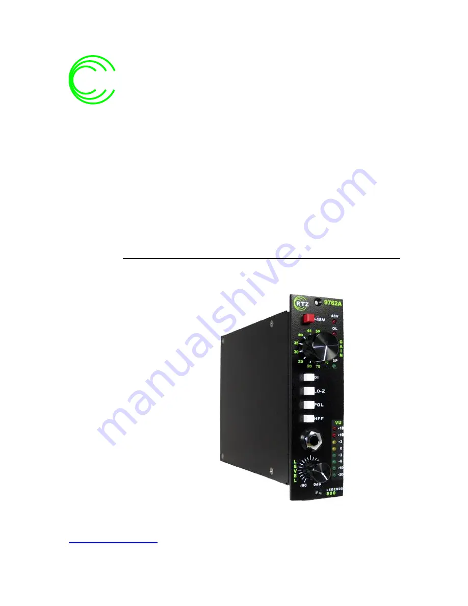
9762A
LEGENDS
500
MICROPHONE
PREAMPLIFIER
Owner’s Manual
RTZ
PROFESSIONAL
AUDIO
Page 1: ...Professional Audio LLC Atlanta GA USA http www rtzaudio com COPYRIGHT 2014 RTZ PROFESSIONAL AUDIO LLC REV A 03 05 12 2014 9762A LEGENDS 500 MICROPHONE PREAMPLIFIER Owner s Manual RTZ PROFESSIO NAL AU...
Page 2: ...5 8 LINE OUTPUT POLARITY INVERT SELECT 10 5 9 100 HZ HIGH PASS FILTER ENABLE 10 5 10 LINE OUTPUT VU METER INDICATOR 10 5 11 DIRECT INPUT DI UNBALANCED 10 5 12 OUTPUT LEVEL CONTROL 10 6 OPERATION 11 6...
Page 3: ...late the vintage 1970s large format consoles i e Neve 1073 Series yet provide a more open and detailed sound by using modern components and transformers We use a super high quality input transformer m...
Page 4: ...s fully transformer isolated to help reduce interference and hum from outside sources However the unit should not be placed near strong magnetic fields or noise sources such as power amplifiers power...
Page 5: ...and interference If you must wire the unit for unbalanced operation keep the cables as short as possible Connect pin 3 of the rack output signal connector to ground for unbalanced operation Note the t...
Page 6: ...tching affects the signal level by roughly 6 dB when switching impedances Miniature sealed gold contact relays are used for all audio switching functions and maximum reliability A separate high impeda...
Page 7: ...nput level is controlled by the master LEVEL control The LEVEL control acts as a channel fader to trim the line amplifier output as needed In general the LEVEL control should be set to the maximum pos...
Page 8: ...r Status Indicator 3 Signal Overload OL Indicator 4 Gain Select Switch 5 Signal Present SP Indicator 6 Direct Input DI Source Select 7 Low Z Microphone Impedance Select 8 Line Output Polarity Invert S...
Page 9: ...on Always start at the lowest gain setting and increase the gain to obtain the desired output level 5 5 Signal Present SP Indicator The SP LED indicates signal activity on the microphone input The det...
Page 10: ...d 20 dB The 0 LED indicates 0 dB output level referenced to 4 dBm 5 11 Direct Input DI Unbalanced The Direct Input is designed for use with instrument sources and is buffered by a Hi Z FET stage to av...
Page 11: ...CW in the 20 dB position and increase the sensitivity to obtain the desired record level If the output level is slightly higher than desired trim the output level back using the LEVEL control The SP s...
Page 12: ...s or dims when power is applied or removed Special ramping circuitry ramps the voltage up and down when power is applied or removed to reduce large pops or bangs in the signal output Allow a second or...
Page 13: ...tinue to glow when the front panel 48V switch is enabled no power flows to the microphone if S1 is on the OFF position Note that switch S1 is provided to ensure that phantom power can never be applied...
Page 14: ...h and Transformer Jumpers 7 4 48V LED Configuration Options JP3 The 48V phantom LED may be configured to indicate the presence of phantom power in two modes The use of external microphone splitter tra...
Page 15: ...f phantom power either internally by 9762A or externally from another source Note that you can completely disable the phantom power and LED via JP3 and the S1 DIP switch The 48V LED can be disabled vi...
Page 16: ...Bu Maximum Maximum Gain 75 dB Frequency Response 20 Hz to 50 kHz 1 5dB Output Distortion THD n 1 THD 22kHz B W Low Z mode 150 Ohms source 27 dBu Input Sensitivity 75 dBu to 20 dBu for 4 dBu output Inp...
Page 17: ...er repair or replace free of charge any product that proves to be defective upon inspection by RTZ Audio or an authorized repair representative This warranty does not cover claims for damage due to ab...