TECHNICAL BULLETIN
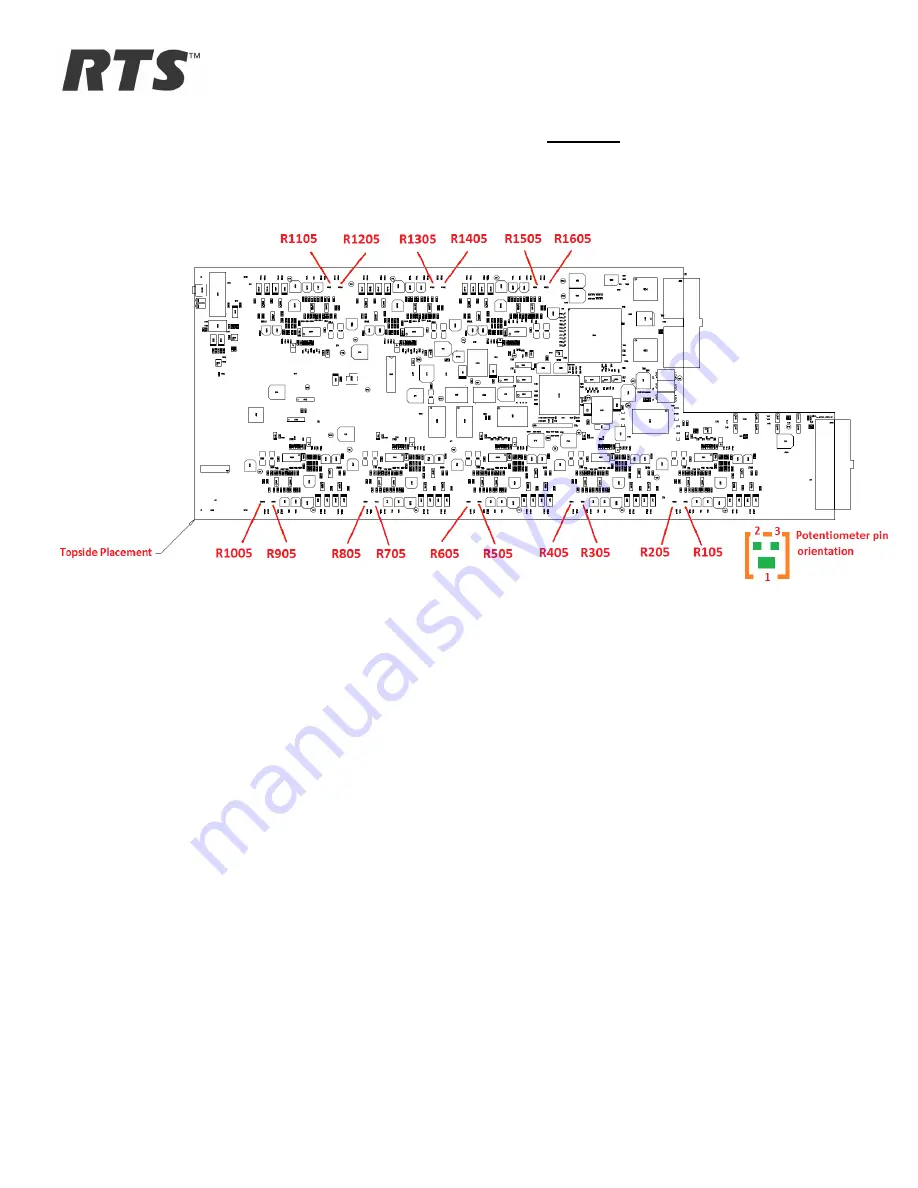
FIGURE 4:
This final mark-up of the assembly print represents the
TOPSIDE
view of the AIO-16 Front Card
and shows the locations of ALL the potentiometers which need to be adjusted on the AIO-16 card.
Page 1: ...R optimization were omitted from the manufacturing process The result is that cards manufactured during this period have unbalanced audio inputs that can be more susceptible to noise on the incoming a...
Page 2: ...channels on the AIO 16 1 3 5 7 9 11 13 and 15 follow the same layout topology around the op amps on the PCBA The even channels on the AIO 16 2 4 6 8 10 12 14 and 16 follow the same layout topology aro...
Page 3: ...e following assembly print shows a BOTTOM view of the AIO 16 Front Card and the location of all eight dual op amps in the AIO 16 design Detail A circled in green shows the op amp U101 associated with...
Page 4: ...rtsintercoms com RTS TB 030 Technical Bulletin 25 June 2014 Page 4 of 7 FIGURE 2 The following drawing shows DETAIL A from the assembly drawing which is a close up of the circuitry surrounding U101 f...
Page 5: ...L BULLETIN FIGURE 4 This final mark up of the assembly print represents the TOPSIDE view of the AIO 16 Front Card and shows the locations of ALL the potentiometers which need to be adjusted on the AIO...
Page 6: ...re the resistance between pin 1 and pin 3 on R105 Use a screwdriver to adjust R105 to the resistance calculated in step 7 10 Recheck the resistance between U101 pin 1 and pin 2 11 Check and record the...
Page 7: ...peat Sections 3 1 and 3 2 for channel 1 and channel 2 above but replace any reference to U101 with U901 Replace any reference to R106 with R906 Replace any reference to R206 with R1006 Replace any ref...