

MOUNTING
The ZW-9 should be located on a secure, flat surface such as a shelf, cabinet or wall, away from other electrical equipment.
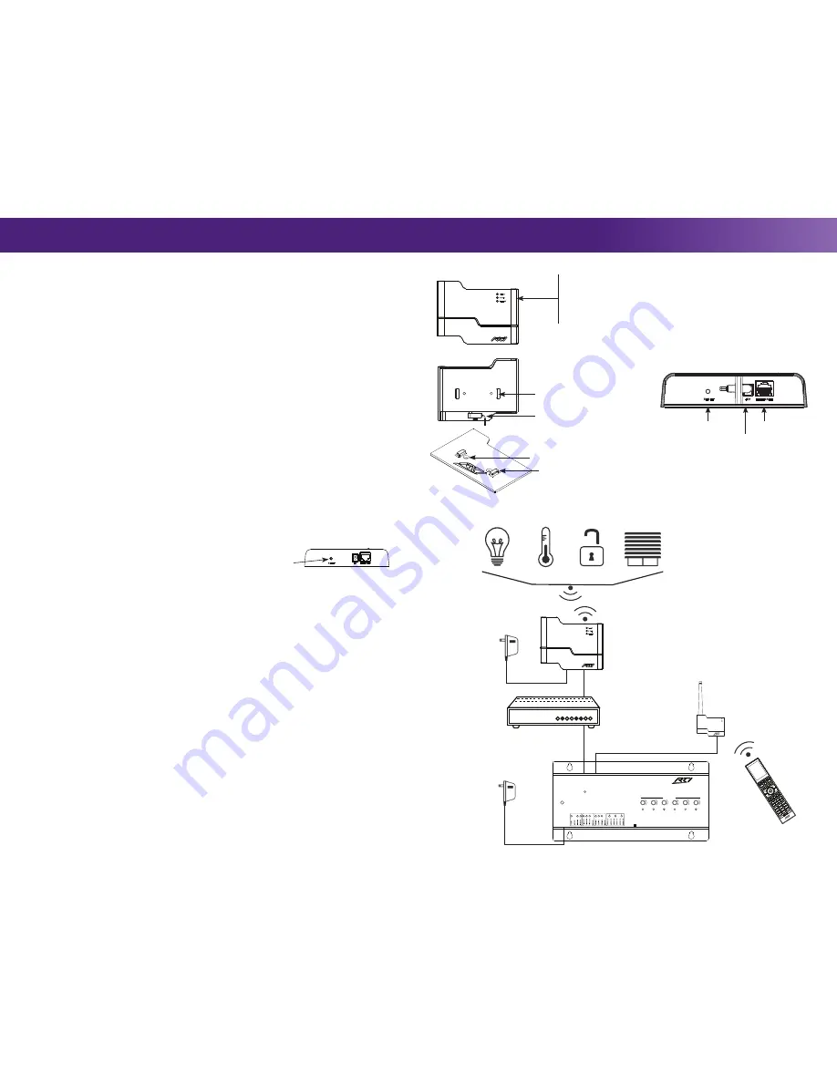
1) Install ZW-9 mounting bracket:
Anchor the ZW-9 mounting bracket using the two (2) #6-32 flathead screws. Wall
mounted installations may require the drywall anchor kit (included).
2) Attach ZW-9 to mounting bracket:
Align mounting holes located on backside of ZW-9 with mounting bracket tabs
and slide the unit downward until snug.
POWERING THE ZW-9
The ZW-9 can be powered using the included power supply or Power over Ethernet (PoE).
•
Power Supply:
Plug the power supply (+5VDC, 2A ) to the power jack.
•
Ethernet Port (Power over Ethernet):
Wire a Cat-5 cable from the ZW-9 Ethernet Port to an 802.3af compliant PoE
switch (Class #2). NOTE: Using a non-compliant PoE device ma
y damage the ZW-9.
COMMUNICATION
The ZW-9 communicates with an RTI XP series control processor via an Ethernet network (LAN).
1) Connect to the Ethernet network:
Connect a Cat-5 cable to the ZW-9 Ethernet port and the LAN router/switch. The
ZW-9 will receive an IP address from the network router via DHCP. The “NET LINK” LED on the front of the ZW-9 will
blink to indicate a connection to the LAN.
2) Add ZW-9 to the Integration Designer system file:
Open the Integration Designer system file, click on the XP
processor and add the ZW-9 as an expansion device under the “Expansion” tab.
3) Enter the MAC address of the ZW-9:
Click on the ZW-9 and select “Edit Expansion Device” and follow the
directions on the screen. (The ZW-9 MAC address can be found on a card in the ZW-9 packaging).
ETHERNET SETTINGS (IP Address)
Setting a static IP address on the ZW-9 is unnecessary and not recommended. For information on IP address settings, visit
the ZW-9 product support webpage located on the RTI dealer website.
NOTE: If static IP address settings are incorrect the ZW-9 will not operate.
How to reset ZW-9 to DHCP
If the ZW-9 is not functioning or is not accessible via the LAN it may be necessary to reset the unit to DHCP.
1)
Press and hold the RESET button.
2)
Power the ZW-9 with the power supply.
3)
Hold the RESET button for 5 seconds.
Z-WAVE NETWORK CONFIGURATION QUICK REFERENCE
For complete instructions on Z-Wave network setup and device programming using the RTI Integration Designer
programming software, visit the ZW-9 product support webpage located on the RTI dealer website.
• Product Inclusion
Start the Add/Include process by selecting Device-Add/Include from the Z-Wave Manager main menu or by selecting
the Add/Include button on the main toolbar. It may take a few moments for the device to show up in the list depending
on how many devices are already in the network and what type of device is being added. When a device is successfully
added you will also hear a beep sound from the computer (if PC sound is enabled).
• Product Exclusion
Start the Remove/Exclude process by selecting Device-Remove/Exclude from the Z-Wave Manager main menu or by
selecting the Remove/Exclude button on the main toolbar. Once the dialog box appears, activate the exclude process on
the device (see the device documentation for more details). As devices are removed from the Z-Wave network they are
removed from the Z-Wave Manager Device List.
ZW-9 Learn Mode
If the ZW-9 is going to be installed in a Z-Wave network with an existing controller, follow these steps to set the learn mode
as the primary or secondary controller.
• Adding the ZW-9 as the Primary Controller
First activate the “include” process on the existing Primary Controller. In the Z-Wave Manager software, select the
“Become Primary” Learn Mode on the Controller toolbar to activate the ZW-9.
• Adding the ZW-9 as a Secondary Controller
First activate the “include” process on the existing Primary Controller. In the Z-Wave Manager software, select the
“Become Secondary” Learn Mode on the Controller toolbar to activate the ZW-9.
The Lifeline Association Group
The ZW-9 supports the Lifeline Association Group. This enables the RTI control system to receive the critical notifications
from Z-Wave devices in the network. Z-Wave Plus devices are automatically associated with the ZW-9 as each is added to
the network. Therefore, when a frame is received such as from a smoke alarm, it is passed on to the XP processor for use
within the RTI system. The Lifeline Signals are processed just like unsolicited messages.
ZW-9 Reset to Defaults Description
NOTE: Use the reset procedure only when the primary controller is missing or inoperable.
Start the ZW-9 reset process by selecting Reset Controller/Start New Installation from the Z-Wave Manager main menu
or by selecting the Reset Controller/Start New Installation button on the main toolbar. The ZW-9 will become the primary
controller, all Z-Wave devices will be removed from its memory and a new HomeID will be assigned.
SCALE 1.000
+5V
RESET
ETHERNET
STATUS
Z DATA
NET LINK
RTI ZW-9 REV 1e
Artwork Template
May 8, 2015
Installation & Operation
ZW-9 Reference
It’s Under Control
®
Product Contents
Contents within the box include the following items:
•
One (1) ZW-9 Z-Wave Interface Module
•
One (1) ZW-9 mounting bracket
•
One (2) Screws (#6-32 x .75”) and drywall anchors
•
One (1) 5VDC/2A power supply
•
One (1) Quick reference guide
•
One (1) Ethernet MAC address card
ZW-9
Z-Wave
®
Interface Module
ZW-9 Reset Button
SCALE 1.000
+5V
RESET
ETHERNET
STATUS
Z DATA
NET LINK
RTI ZW-9 REV 1e
Artwork Template
May 8, 2015
Ethernet Port
Reset Button
5VDC/2A
Power Plug
SCALE 1.000
+5V
RESET
ETHERNET
STATUS
Z DATA
NET LINK
RTI ZW-9 REV 1e
Artwork Template
May 8, 2015
Ethernet Switch
ZW-9
Interface Module
Power Supply
RESET
ETHERNET
EXPANSION
PORT 1
PORT 2
PORT 3
PORT 4
PORT 5
PORT 6
+
+
+
+
+
+
USB
RTI COM
POWER
STATUS
RS-232
POWER / IR
+12VDC T3-24VDC SENSE RELAYS (+30VDC, 5A MAX)
IR OUTPUT LEVEL
1
2
Model
XP-6
Advanced Control Processor
Power Supply
XP-6 Control Processor
ZM-24 Transceiver Module
RTI Remote Control
Example Wiring Diagram
TITLE
REMOTE TECHNOLOGIES INC.
SHAKOPEE, MN 55379
ZW-9 TOTAL ASSEMBLY
+5V
RESET
ETHERNET
ZW-9 STATUS LIGHTS
•
STATUS:
Flashes to indicate the unit has been powered. Lit
solid indicates the unit is powered and communicating with
an RTI control processor via the Ethernet network.
•
Z DATA:
Flashes to indicate Z-Wave network activity.
•
NET LINK:
Flashes to indicate Ethernet network activity.
ZW-9 Front
TITLE
REMOTE TECHNOLOGIES INC.
SHAKOPEE, MN 55379
ZW-9 TOTAL ASSEMBLY
+5V
RESET
ETHERNET
ZW-9 Rear
ZW-9 Bottom
Power Supply Plug
Mounting Bracket Holes
TITLE
REMOTE TECHNOLOGIES INC.
SHAKOPEE, MN 55379
ZW-9 TOTAL ASSEMBLY
+5V
RESET
ETHERNET
Mounting Bracket Screw Holes (2)
Mounting Bracket Tabs (2)
ZW-9 Mounting
Bracket
Z-Wave Enabled Devices


