

It’s Under Control
®
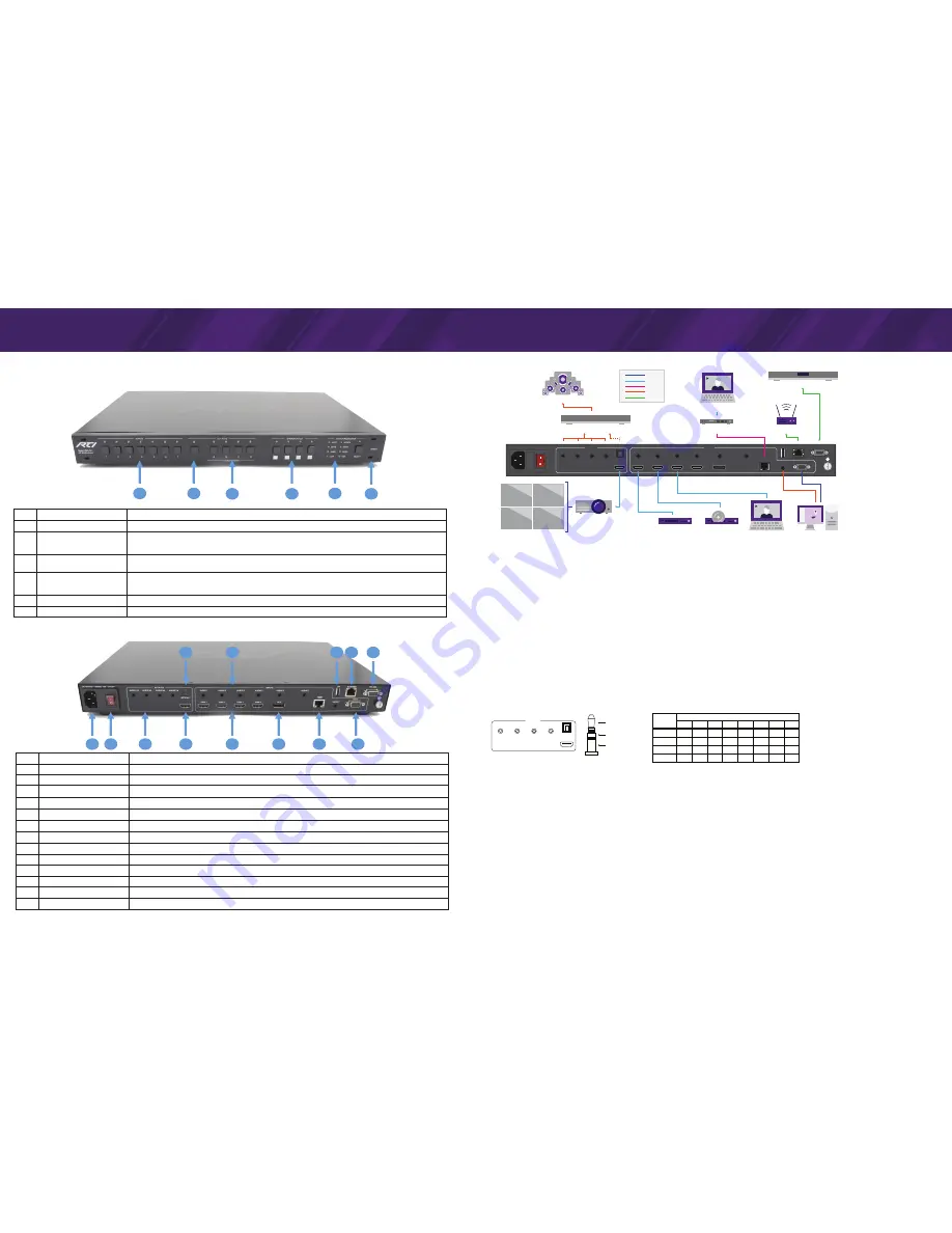
FRONT PANEL DESCRIPTION
Installation & Operation
No.
Name
Function
1
Video Input
Press to select the video input (buttons 1-7) for the video windows and audio output.
2
Audio Source
To select the audio source, press the Audio Select button, then press the Video Input button (1-7) or the Video
Window button (A-D). The currently selected audio source button will be lit solid and other buttons will flash.
NOTE: If a Video Window button is selected, the audio source will be the video input assigned to that window.
3
Video Window
Each Video Window button (A-D) represents one of the four possible video windows used in window layouts. To
change the video source assigned to a window, select button A, B, C or D then press the video input (1-7).
4
Window Layout
Press button to select from preset window layouts containing up to four video windows.
NOTE: The default window layouts are shown below each button. The preset window layouts assigned to these
buttons may be adjusted via the web interface (16 available layout options).
5
Output Resolution
Press Select button to scroll through resolutions. Currently selected resolution will be lit.
6
Power Indicator
Turns red when power on
No.
Name
Function
1
AC 110-240V
Connect AC power cable
2
Power switch
Turn VMS-741 on or off
3
Audio Output
4 - 3.5mm Stereo analog audio outputs (8 channel) - Connect to audio system. (see Audio Output Options)
4
Optical Output
TOSLINK optical audio output - Connect to audio system.
5
HDMI Output
HDMI port - Connect to HDMI display.
6
Audio Input
7 - 3.5mm Stereo analog audio inputs - Connect to audio output of source device.
7
HDMI Input
4 - HDMI Ports - Connect to HDMI source device.
8
DisplayPort Input
DisplayPort - Connect to DisplayPort source device
9
HDBaseT Input
RJ-45 Jack - Connect to HDBaseT Transmitter
10
VGA Input
VGA port - Connect to VGA source device
11
FW
USB port for firmware update
12
Ethernet
RJ-45 Jack - Connect to Ethernet network
13
RS-232
Serial DB9 - Connect RS-232 control device
CONNECTION DIAGRAM
10
11 12
13
9
8
4
6
1
2
3
5
7
1
2
3
4
5
6
AUDIO 1/2
ON/OFF
AC110-240V ~ 50/60Hz 15W
AUDIO 3/4
AUDIO 5/6
AUDIO 7/8
AUDIO 1
AUDIO 2
AUDIO 3
AUDIO 4
AUDIO 5
DP 5
AUDIO 6
FW
AUDIO 7
VGA 7
ETHERNET
RS-232
HDBT
HDMI 1
HDMI 2
HDMI 3
HDMI 4
OPTICAL 1
OUTPUTS
INPUTS
Projector
Window 3
Window 4
Window 1
Window 2
Control System
Audio Amplifier or Receiver
Satellite
Blu-ray
HDBaseT Transmitter
Router
Laptop
Laptop
Video
HDMI
HDBaseT
Audio
Control
7.1 Analog Audio
Desktop
INSTALLATION
Please visit the RTI dealer portal (www.rticorp.com/dealer) for additional instructions and specifications.
RACK MOUNTING
1. Remove Feet.
2. Install Rack Mount Brackets using supplied screws.
3. Mount in rack.
CONNECTIONS
1. Connect HDMI/VGA/DP/HDBaseT source devices to input ports (as needed).
2. Connect a display device such as a TV or projector to the HDMI OUT port.
3. Connect the audio source devices to the audio inputs (as needed).
4. Connect the analog audio outputs or TOSLINK optical audio output to an audio system such as a receiver or amplifier (See below for details).
5. Connect the serial output of a control system to the RS-232 port (as needed).
6. Connect the ETHERNET port to Ethernet network for access to web interface and IP control via a two-way driver (available via rticorp.com/dealer).
7. Connect power cable to the VMS-741 and power the unit on.
AUDIO INPUT/OUTPUT
To select between the HDMI/DP/HDBaseT audio inputs or the analog inputs, access the web interface General tab (instructions below) and set the Audio Input Configuration to
“Auto” for the embedded HDMI/DP/HDBaseT audio, or “External” for the 3.5mm Stereo analog inputs.
NOTE: If the analog audio outputs are used, the audio format for the selected input must be either analog stereo or uncompressed PCM audio with up to 8 channels (7.1).
The VMS-741 has three audio output types:
•
Embedded, HDMI
•
Digital Optical, TOSLINK
•
7.1 Channel Analog, 4 x 3.5mm Stereo (Pinout and audio format chart below)
RS-232 CONTROL
An RTI control system driver is available for the VMS-741 via the rticorp.com driver store. Follow the instructions that come packaged with the driver.
•
Connect to the VMS-741 to a control system using a straight-through serial cable with a DB9 connector.
•
Default: baud rate: 9600; data bits: 8; stop bits: 1; parity: none
ETHERNET/IP CONTROL
An RTI control system driver is available for the VMS-741 via the rticorp.com driver store. Follow the instructions that come packaged with the driver.
•
The VMS-741 is set to use DHCP by default and the network router must have DHCP enabled. Wire the VMS-741 to the Ethernet network using Cat cable with the RJ-45
termination and power the unit on. The network router will assign an IP address to the unit automatically and allow it to join the network.
•
The IP address will be shown on the video display when the VMS-741 is powered on and when a video input is selected that does not have a source connected to it.
WEB INTERFACE
The VMS-741 web interface is used for configuring settings (see below). To access the web interface, first determine the IP address that was assigned to the VMS-741 (see
above) and enter it into the search bar of a standard web browser (ex 10.10.0.100).
Web Interface Settings:
•
General:
Video input and window layout selection, Audio configuration, Button Configuration.
•
Advanced:
Audio settings, RS-232 Baudrate, Audio and video OSD, Analog settings.
•
EDID:
EDID - Copy (Ports 1-7), EDID Upload and Download
•
Network:
DHCP, IP settings, Socket settings, Reset network settings to factory default.
Features and specifications subject to change without notice.
VMS-741
4K MultiViewer
AUDIO 1/2
AUDIO 3/4
AUDIO 5/6
AUDIO 7/8
OPTICAL 1
OUTPUTS
AU D I O
F O R M AT
2.0
2.1
5.1
7.1
AU D I O O U T P U T C H A N N E L
1
2
3
4
5
6
Left (1, 3,5,7)
Right (2,4,6,8)
Ground
7
8
L
R
—
—
—
—
—
—
L
R
LFE
—
—
—
—
—
FL
FR
LFE
FC
RL
RR
—
—
FL
FR
LFE
FC
RL
RR
RLC
RRC
AUDIO 1/2
AUDIO 3/4
AUDIO 5/6
AUDIO 7/8
OPTICAL 1
OUTPUTS
AU D I O
F O R M AT
2.0
2.1
5.1
7.1
AU D I O O U T P U T C H A N N E L
1
2
3
4
5
6
Left (1, 3,5,7)
Right (2,4,6,8)
Ground
7
8
L
R
—
—
—
—
—
—
L
R
LFE
—
—
—
—
—
FL
FR
LFE
FC
RL
RR
—
—
FL
FR
LFE
FC
RL
RR
RLC
RRC