


It’s Under Control
®
insTallaTiOn nOTes:
The RP-4 does not support any RTI wired interfaces (In-wall touchpanels, keypads, etc).
It is not possible to add additional RM-433 433MHz RF antennas and ZM-24 Zigbee transceivers.
The RP-4 supports one-way control via the RTiPanel App (NOTE: Virtual Panel is NOT supported).
If an RTiPanel device is in the Integration Designer system file, the computer used to download to the RP-4 must have an Internet connection.
insTallinG The anTenna
Insert the antenna on to the RP-4 BNC connector and twist the collar clockwise until it locks into place.
POweRinG The RP-4
The included AC adapter should be connected to the POWER jack on the RP-4 or the 12VDC/Ground terminals (see below). The power LED will turn-on.
NOTE: Use only the supplied AC adapter (12VDC Power Supply) to power the RP-4.
COnneCTiOns
COnneCTinG iR emiTTeRs
The four (4) IR emitter ports on the RP-4 are compatible with industry standard infrared emitters and connecting blocks. Each output port is capable of driving up to two
infrared emitters directly. More than two infrared emitters per port requires an amplified connecting block. A connecting block can be wired up to 1000 feet away from the
RP-4 using #22 AWG (minimum) wire.
adJusTinG iR OuTPuT Gain
The IR output gain can be separately adjusted for each of the four output ports. The RP-4 is shipped with the IR gain set to the optimum level for most equipment, and
it should only need to be adjusted if the attached equipment is not responding reliably. If adjustment is needed, rotate the IR output controls on the front of the RP-4
clockwise for higher output power, or counter-clockwise for lower output power.
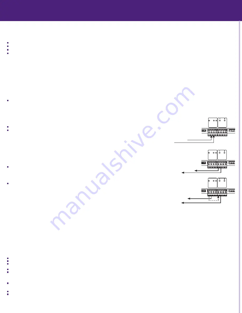
vOlTaGe sense
The RP-4 has two voltage sense inputs (+3-24 VDC) that are configurable within Integration Designer. Based on the status
of the voltage sense input, macros can be programmed to trigger IR commands, RS-232 commands, relay closure, etc.
Connect the positive lead from voltage source to the RP-4 Sense In 1 or 2 terminal.
Connect the negative lead from the voltage source to the RP-4 Ground terminal.
Relays
The two relays in the RP-4 can provide contact closure or switching control for loads up to 5A/30VDC each. Both relays are
Normally Open when not energized, but they can be programmed to behave Normally Closed as long as power is applied
to the RP-4. The RP-4 relays can also be used as voltage (12VDC) triggers which requires additional wiring (see below).
For equipment that requires a momentary trigger, a macro will need to be created which closes the relay, has a
short time delay (.2-.5 second), then opens the relay.
For Contact Closure Control:
1. Connect the Contact A and B terminals of an RP-4 relay to the equipment being controlled.
For voltage Trigger (12vdC) Control:
1. Connect the Ground terminal of the RP-4 to the ground connection on the equipment to be triggered.
2. Install a jumper wire (#22 AWG) between the +12VDC and Contact A terminal of the relay being
used on the RP-4.
3.
Connect the Contact B terminal of a relay to the 12VDC power input on the equipment being triggered.
eTheRneT
This RJ-45 port allows connection to a 10/100 Base-T Ethernet network (LAN) for programming updates and one-way control with RTiPanel devices. Network settings such as
the IP address are configurable within Integration Designer.
NOTE: The RP-4 does not support control of devices via IP.
usb PORT
A standard USB B port (the type found on most printers) is used to download the Integration Designer programming software or firmware updates into the RP-4.
PROGRamminG & OPeRaTiOn
PROGRamminG The RP-4
The RP-4 must be programmed to operate. All programming is done using RTI’s Integration Designer software and is downloaded using the USB port or over Ethernet. The
software allows you to create actions (e.g. commands and macros) that are associated with button presses on RTI wireless interfaces or RTiPanel devices. The software
automatically creates all of the system trigger codes, and generates the correct download for every device in the system.
NOTE: It is recommended that the firmware is updated on the RP-4 to the latest version. Check for the latest firmware version on the dealer section of the RTI website.
NOTE: If an RTiPanel device is in the Integration Designer system file, the computer used to download to the RP-4 must have an Internet connection.
The sTaTus led
The status LED will illuminate red and stay red if there is no Integration Designer system file installed on the RP-4.
The status LED will illuminate green while the RP-4 firmware is being updated. Once the firmware is finished updating, the status LED will shut off.
The status LED will illuminate green while the RP-4 is loading the Integration Designer system file that is installed. Once finished loading, the status LED will shut off.
NOTE: If an RTiPanel device is in the Integration Designer system file, the status light will remain off while the RTiPanel files are being uploaded (this may take a little while).
The status LED will flash red while the RP-4 is powering up. Once the RP-4 is booted up, the LED will shut off (assuming a system file is loaded).
The status LED will illuminate green if a valid system trigger code is detected. The LED will stay on while the RP-4 is busy processing the action associated with the trigger
code.
neT link led
The Net Link LED will illuminate if the RP-4 is connected to an Ethernet network. The LED will flash intermittently dependent upon traffic.
RF link led
The RF Link LED blinks green when the RP-4 receives an transmission at 433MHz from an RTI remote control.
The RF Link LED blinks red when the RP-4 receives an transmission at 433MHz from an unrecognized device.
seTTinG The ZOne COde
If the RP-4 is installed in close proximity to other RTI control systems using 433MHz RF, the system Zone Code can be changed in the Integration Designer software. This
allows up to 256 separate control systems to operate in the same general area, such as multi-dwelling units or homes with more than one media system.
installation & Operation
Fastener Holes (4)
Model
RP-4
Remote Control Processor
ETHERNET PORT 1 PORT 2 PORT 3 PORT 4
Sense Inputs: +3-24VDC
Relays: +30VDC, 5A max
IR OUTPUT LEVEL
POWER USB
RESET
STATUS NETLINK RF LINK
POWER / SENSE RELAYS
+12VDC
GROUND
SENSE IN 1
SENSE IN 2
CONT
ACT A
CONT
ACT B
CONT
ACT A
CONT
ACT B
+12vdC voltage Trigger wiring
Model
RP-4
Remote Control Processor
ETHERNET PORT 1 PORT 2 PORT 3 PORT 4
Sense Inputs: +3-24VDC
Relays: +30VDC, 5A max
IR OUTPUT LEVEL
POWER USB
RESET
STATUS NETLINK RF LINK
POWER / SENSE RELAYS
+12VDC
GROUND
SENSE IN 1
SENSE IN 2
CONT
ACT A
CONT
ACT B
CONT
ACT A
CONT
ACT B
Contact Closure wiring
To equipment ground
To equ12VDC input
Model
RP-4
Remote Control Processor
ETHERNET PORT 1 PORT 2 PORT 3 PORT 4
Sense Inputs: +3-24VDC
Relays: +30VDC, 5A max
IR OUTPUT LEVEL
POWER USB
RESET
STATUS NETLINK RF LINK
POWER / SENSE RELAYS
+12VDC
GROUND
SENSE IN 1
SENSE IN 2
CONT
ACT A
CONT
ACT B
CONT
ACT A
CONT
ACT B
To equipment ground
To equ12VDC output
voltage sense wiring
To equipment being controlled


