

RTD Alarm Setter Transmitter
□
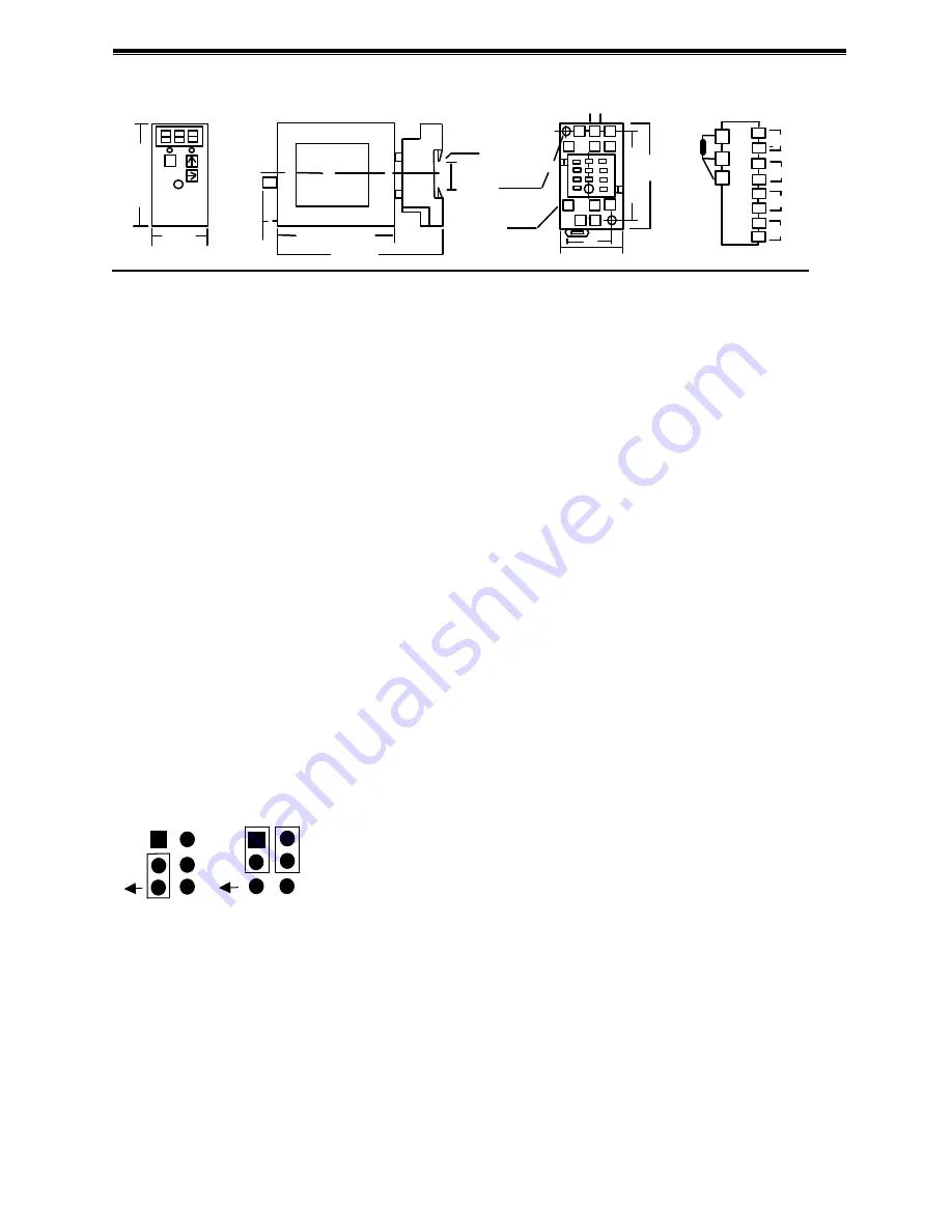
EXTERNAL
DIMENSIONS
:
:
:
:
mm (inch)
27
27
27
27
8888
89
89
89
89
119
119
119
119
70
70
70
70
DIN RAIL
DIN RAIL
DIN RAIL
DIN RAIL
35mm wide
35mm wide
35mm wide
35mm wide
35.4
35.4
35.4
35.4
1111
2222
3333
4444
5555
6666
7777
8888
9999
10
10
10
10
11
11
11
11
6666
6666
MTG HOLE
MTG HOLE
MTG HOLE
MTG HOLE
2-4.2*5
2-4.2*5
2-4.2*5
2-4.2*5
11-M3
11-M3
11-M3
11-M3
SCREW
SCREW
SCREW
SCREW
29.5
29.5
29.5
29.5
22
22
22
22
72
72
72
72
59
59
59
59
1111
2222
4444
10
10
10
10
11
11
11
11
+
-
POWER
POWER
POWER
POWER
7777
8888
3333
6666
5555
9999
++++
SD
SD
SD
SD
output
output
output
output
S1
S1
S1
S1
S2
S2
S2
S2
A
AA
A
B
BB
B
bbbb
□
TERMINAL CONNECTIONS :
Connect the unit as in the above diagram or refer to the connection diagram label on the side of the unit.
□
SETTING VALUE ADJUSTMENT
:
:
:
:
■
Key Description
:
S.D
:
SELECT
↑:
UP (change enumeration)
→:
RIGHT (move digit)
■
Function Key
:
5 1
S 1 setting value 0
400.0 5 2
S 1 nonmoving zone 0
99.9 5 3
S 1 moving time delay 0
999 sec.
5 4
S 2 setting value 0
400.0 5 5
S 2 nonmoving zone 0
99.9 5 6
S 2 moving time delay 0
999 sec.
5 7
S 1
S 2 setting type.(1=Hi. 0=Lo) Hi-Hi. Hi-Lo. Lo-Hi. Lo-Lo user selectable.
5 8
Start Delay Time 0
999, input start from zero, no alarming movement within the time.
5 9
71 DA-Percent setting value 0
99.9, high terminal analogy answers to RTD temperature.
5 9
72 SPAN digit adjustment (long press adjust rough
、
short press adjust detail
)
5 9
73 ZERO digit adjustment (long press adjust rough
、
short press adjust detail
)
5 9
99 Save.
■
Adjust output value SPAN
、
ZERO.
Press "SD", enter 59, adjust display to "72" condition, operate "
↑→
", adjust SPAN output value. (long / short press
adjust rough / detail)
Press "SD", enter 59, adjust display to "73" condition, operate "
↑→
", adjust ZERO output value.(long / short press
adjust rough / detail)
Read output signals from terminal 7 and 8.
□
ANALOGY OUTPUT VOLTAGE CURRENT EXCHANGE
:
:
:
:
Disassemble box. Install and skip one pin as follows:
mA output
V output
J1 J1
□
CHECKING
:
:
:
:
■
Terminal wiring
:
Check that all cables are correctly connected according to the connection diagram.
■
Power input voltage
:
Check voltage of the terminal 10
、
11.
■
Input
:
Check that the input signal is within 0-100
%
.
■
Output
:
Check analogy output and alarming function movement meets the described specifications.
□
SETTING PROCEDURE
:
:
:
:
■
This unit is calibrated at the factory to meet the ordered specifications; therefore you usually do not need any
calibration.
■
30 sec. nonmoving key returns to normal display value.
■
During RTD, 3digits display -104
~
0
、
0
~
99.9
、
100
~
700 or other -19.9
~
99.9.
■
For matching the signal to a receiving instrument, adjust the setting as explained.