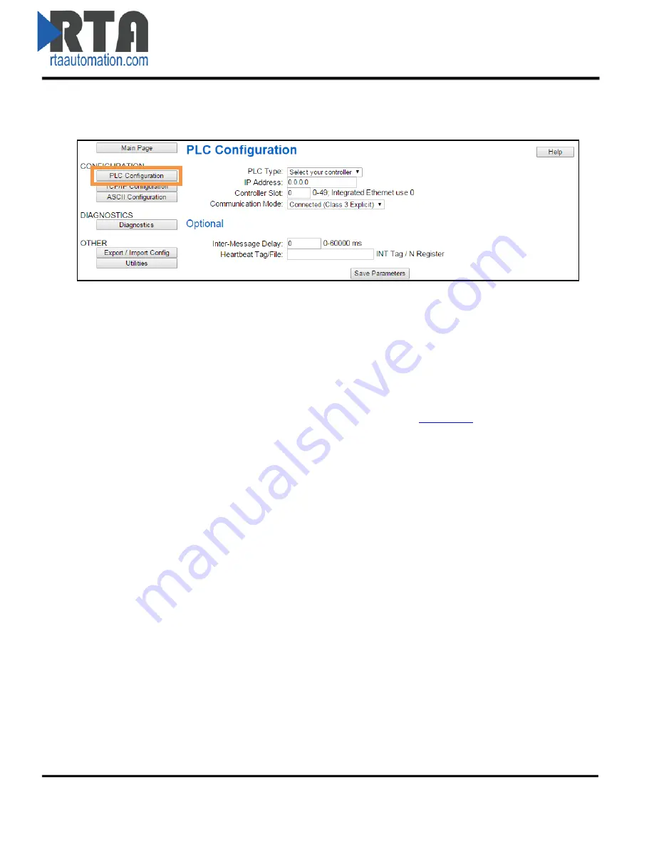
PLC Configuration
1)
Click the
PLC Configuration
button under the
CONFIGURATION
section.
2)
PLC Type: Select which PLC you are using.
a.
If using a Logix PLC, all processors are compatible.
b.
If using a PLC5E, then it must be: Series C, Revision N.1 or later; Series D, Revision E.1 or
later; or Series E, Revision D.1 or later.
c.
If using a SLC5/05, then it must be: Series A, Version OS501; or FRN5 Series B and Series
C or later.
d.
If using a NetENI module, select based on the Processor it is connected to.
e.
If connecting to an I/O Scanner, please see User Guide,
Appendix B
for more details.
3)
IP Address: Enter the IP Address of the PLC.
a.
If using I/O Scanner, this is the IP Address of the PLC.
i.
If the IP Address is 0.0.0.0, the gateway will accept messages from any device.
4)
Controller Slot: Enter the slot that the Controller is located in.
a.
If you are using an Integrated Ethernet Card, enter slot 0.
b.
For Logix processors, this is
NOT
the slot of the Ethernet Adapter.
5)
Communication Mode: Select whether to use unconnected or connected messaging.
a.
Connected Messaging
(Default): Relies on reserved resources to transfer data to/from
the PLC. This is more reliable than Unconnected Messaging.
b.
Unconnected Messaging
:
R
elies on shared resources to transfer data to/from the PLC.
This could result in message timeouts if there are a lot of devices fighting for these
shared buffers.
6)
Inter-Message Delay: The Inter-Message Delay is a forced delay for each request the gateway
sends to the PLC.
a.
This setting will affect the speed at which a message is delivered and the amount of
traffic the gateway adds to the network.
Real Time Automation, Inc.
12
1-800-249-1612


