background image


DT2306 Potentiometer Data Logger Manual 


ELM0075B 


Page 1  


I

NTRODUCTION


F

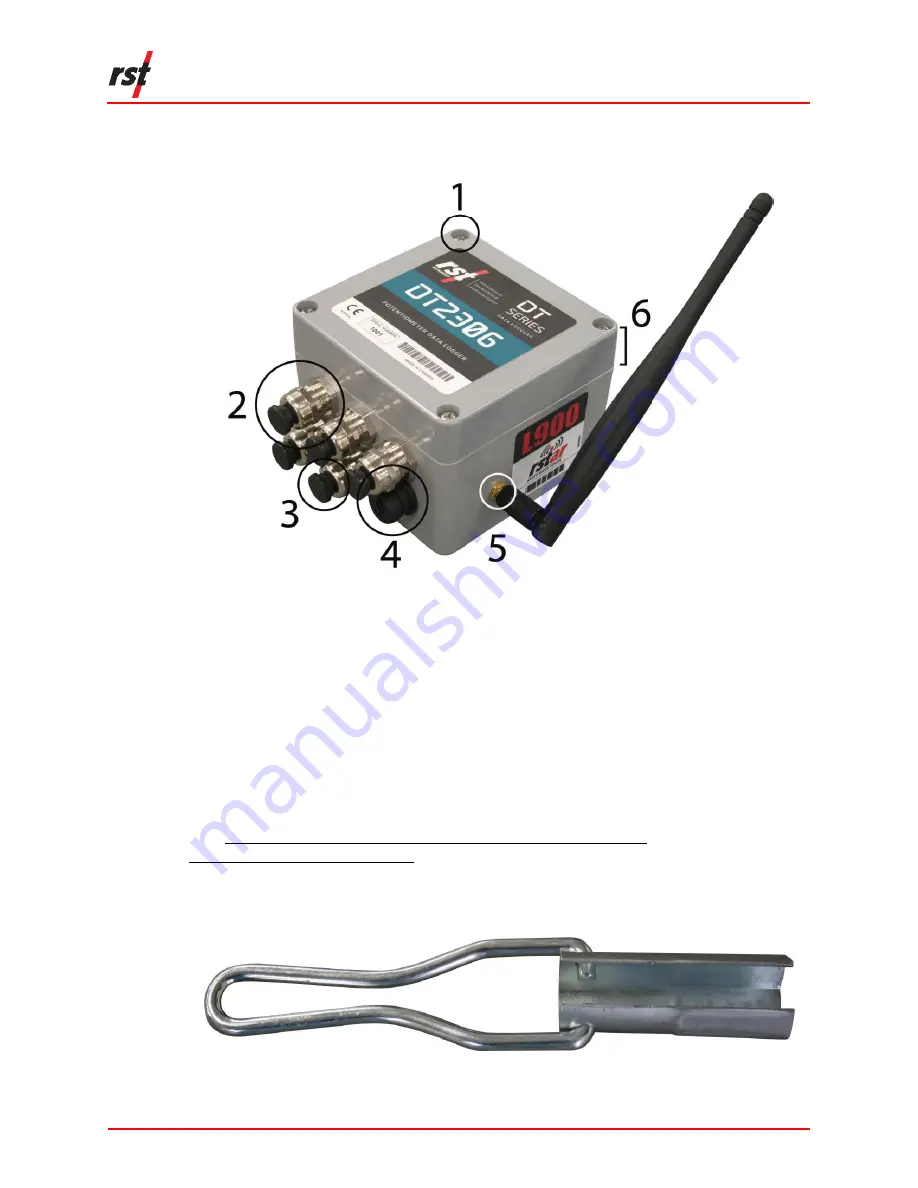
IGURE 

1-1


DT2306

 POTENTIOMETER DATA LOGGER 


Philips screw 

Cable gland 

Black cable plug 

USB port 

RSTAR/DT Link antenna 

Logger lid 

 
A mini-B USB connector cable and RST Resource DVD are included in a standard 
DT2306 data logger shipment.  

Contact RST Instruments if any items are missing from the shipment. 

Visit https://www.rstinstruments.com/Geotechnical-Videos.html or 
https://youtu.be/a5hHQaN1NkI for an instructional installation video. 

An optional Cable Gland Nut Wrench may be purchased from RST for effortless 
cable gland access. Contact RST for more details. 


F

IGURE 

1-2


C

ABLE GLAND NUT WRENCH 


Summary of Contents for DT2306

Page 1: ...om ELM0075B All efforts have been made to ensure the accuracy and completeness of the information contained in this document RST Instruments Ltd reserves the right to change the information at any time and assumes no liability for its accuracy Copyright 2019 RST Instruments Ltd All rights reserved Document Number ELM0075B Release Date April 18 2019 DT2306 Potentiometer Data Logger Manual ...

Page 2: ...DT2306 Potentiometer Data Logger Manual ELM0075B Page i TABLE OF REVISIONS Rev Revision History Date Prepared By Approved By B Initial release 18 Apr 2019 MP JW ...

Page 3: ...tware Installation 2 3 3 Potentiometer Connection 3 4 LOGGER CONFIGURATION 8 4 1 Logging Tab 8 4 2 Status Tab 9 4 3 Data View Tab 11 4 4 Monitor Tab 11 4 4 1 Graphical Monitor 12 4 5 Sensors Tab 13 4 6 Connections Tab 15 5 TROUBLESHOOTING 16 6 BATTERY INFORMATION 17 6 1 Battery Type 17 6 2 Estimated Battery Life 17 6 3 Changing the Battery 18 7 SERVICE AND REPAIR 19 ...

Page 4: ...ure 3 7 Tighten screws in the following order and pattern 6 Figure 3 8 Mini B USB port 7 Figure 3 9 Port and status indicators 7 Figure 4 1 The logging tab 8 Figure 4 2 The status tab 10 Figure 4 3 Data view tab 11 Figure 4 4 The monitor tab 12 Figure 4 5 Graphical monitor options 13 Figure 4 6 Sensor tab 14 Figure 6 1 Tighten screws in the following order and pattern 19 LIST OF TABLES Table 4 1 L...

Page 5: ...cable and RST Resource DVD are included in a standard DT2306 data logger shipment Contact RST Instruments if any items are missing from the shipment Visit https www rstinstruments com Geotechnical Videos html or https youtu be a5hHQaN1NkI for an instructional installation video An optional Cable Gland Nut Wrench may be purchased from RST for effortless cable gland access Contact RST for more detai...

Page 6: ...MPT TO RECHARGE THE BATTERY DO NOT REPLACE THE BATTERY WITH AN ALKALINE OR ZINC CARBON BATTERY REMOVE STANDARD BATTERIES PRIOR TO SHIPPING THE DT2306 3 INSTALLATION 3 1 INSTALLATION TOOLS AND MATERIALS Desktop or laptop computer with USB port Supported operating systems include Microsoft Windows Vista 7 8 and 10 Phillips 2 screwdriver Flat head 2 5 mm screwdriver Two 20 mm open wrenches or small c...

Page 7: ...OT INSTALL IN FLOODABLE LOCATIONS THE LOGGER IS RAIN TIGHT ONLY AND NON SUBMERSIBLE NOTE THE PICTURES IN THIS SECTION ARE INSTRUCTIONAL AND MAY FEATURE A LOGGER OTHER THAN THE DT2306 TO ILLUSTRATE THE INSTRUCTIONS 1 Loosen the cable gland using two 20 mm wrenches Hold the bolt in place with one wrench Loosen the cap with the other wrench Refer to Figure 3 1 for proper wrench placement Refer to Fig...

Page 8: ... Refer to Figure 3 3 FIGURE 3 3 REMOVE THE CABLE PLUG FROM THE CABLE GLAND 3 Loosen the 4 Phillips screws on the top of the logger Lift the cover off 4 Insert the sensor cable with stripped wire ends through the cable glands and into the logger Ensure the cable sheathes are inside the enclosure 5 Connect the leads Refer to Figure 3 4 CAUTION ENSURE NO BARE WIRES ARE VISIBLE ...

Page 9: ...ecure the wires to the logger circuit by tightening each wire with a 2 5 mm flat blade screwdriver 7 Tighten the cable glands using the same wrench positioning as step 1 Refer to Figure 3 5 Tug gently on the cable after each half turn to inspect cable mobility FIGURE 3 5 TIGHTENING THE CABLE GLAND ...

Page 10: ...formation regarding the types of batteries suitable for this logger Place the adapter into the battery holder For radio enabled loggers place the battery into the battery holder Roll the battery back and forth to clean the contacts If the batteries are already installed hold the battery in place and pull the tab out to activate the logger Refer to Figure 3 6 FIGURE 3 6 ACTIVATE THE BATTERY 10 Repl...

Page 11: ... cover of the mini B USB port Refer to Figure 3 8 FIGURE 3 8 MINI B USB PORT 12 Connect the supplied USB connector cable to the DT2306 data logger and computer s USB port Launch the DT Logger Host software Wait for the port and status indicator to turn green Refer to Figure 3 9 Refer to Section 5 if the indicators do not turn green FIGURE 3 9 PORT AND STATUS INDICATORS ...

Page 12: ...1 LOGGING TAB Configure the logger in the Logging Tab Figure 4 1 prior to data collection Refer to Table 4 1 for Logging settings and descriptions NOTE SOME LOGGER CONFIGURATION PARAMETERS WILL BE CONTROLLED BY THE RTU BASE STATION WHEN THE LOGGER IS IN RSTAR ENABLED MODE ANY SUCH PARAMETERS WILL BE INACCESSIBLE BY THE DT LOGGER HOST SOFTWARE CAUTION DATA LOSS WARNING ENSURE THE DATA HAS BEEN DOWN...

Page 13: ...en logger memory is full This option is recommended for locations with access issues where data may not be retrieved prior to battery failure C Clock Options Select a custom date and time or click Sync to computer date time to sync it to the computer s current date and time Select Auto sync date time to always sync to the computer s date time when connected via USB D Logger Label Type a custom nam...

Page 14: ...er displayed matches the logger serial number Click Collect Data to download the data into a csv file A prompt will appear asking to append or overwrite data Append will continue to add data to existing readings in the memory Overwrite data will erase all data in the logger and restart the logging process ...

Page 15: ...ew of logger data files Figure 4 3 FIGURE 4 3 DATA VIEW TAB NOTE DATA VIEW DISPLAYS MAJOR DATA LOGGER SETTINGS AND ALL SAVED DATA RECORDS USE A TEXT FILE VIEWER OR SPREADSHEET PROGRAM E G MICROSOFT EXCEL TO VIEW THE ENTIRE FILE 4 4 MONITOR TAB The following section details the features of the Monitor Tab Figure 4 4 ...

Page 16: ... update approximately every two seconds when successfully connected to the data logger A green indicator will flash each time a sensor data is updated The program will display in each Sensor Reading field until communication is established with the data logger The program will display RANGE_ERR when the Sensor Reading is outside of valid range 4 4 1 Graphical Monitor Click the Graph button to invo...

Page 17: ...usted between 1 120 minutes Click the Settings button to open the Graph Settings dialog and manipulate graph properties such as line style background color and grid lines Figure 4 5 FIGURE 4 5 GRAPHICAL MONITOR OPTIONS 4 5 SENSORS TAB The sensors tab shows current sensor configurations Figure 4 6 Readings can be adjusted from to Engineering Units if desired Data required for the conversion to engi...

Page 18: ...DT2306 Potentiometer Data Logger Manual ELM0075B Page 14 FIGURE 4 6 SENSOR TAB Refer to Table 4 2 for Sensors settings and descriptions ...

Page 19: ...r Click to update logger with current sensor settings Note Upload to Logger must be clicked to update logger with new settings CAUTION DATA LOSS WARNING THE PROGRAM WILL PROMPT THE USER TO RESTART LOGGING OR ERASE DATA CURRENTLY CONTAINED IN THE LOGGER CURRENT READINGS AND ALL PREVIOUS DATA WITH CURRENT SENSOR CALIBRATION SETTINGS WILL BE DOWNLOADED TO A CSV FILE NEXT TIME DATA IS COLLECTED IF THE...

Page 20: ...button to activate the help system Answers to common problems and troubleshooting tips may be found by browsing help topics or by searching keywords TABLE 5 1 COMMON TROUBLESHOOTING PROBLEMS AND SOLUTIONS PROBLEM SOLUTION Failed Drivers Installation Manual installation of the USB drivers Start Menu RST Instruments DT Logger Host software Tools Install USB Drivers Status Message Port Not Open Close...

Page 21: ...ttery options are designed to support the same level of performance in the DT 2306 and are considered equivalent TABLE 6 1 BATTERY TYPES BATTERY NAME BATTERY TYPE APPLICATION Standard Battery SAFT LSH 20 D Cell or equivalent Radio enabled loggers RSTAR DT Link Compact Battery One SAFT LSH 14 Light C Cell or two SAFT LS 14500 AA with appropriate adapter Stand alone loggers CAUTION DO NOT ATTEMPT TO...

Page 22: ...tery life is 20 or less 6 3 CHANGING THE BATTERY The following steps outline the procedure to change the battery CAUTION CONNECT THE DATA LOGGER TO THE DT LOGGER HOST SOFTWARE AND RE APPLY LOGGING SETTINGS AFTER BATTERY REPLACEMENT TO ENSURE TIME SETTINGS ARE CORRECT FAILURE TO RE APPLY SETTINGS COULD RESULT IN IMPROPER TIME STAMPS AFTER BATTERY REPLACEMENT 1 Connect the data logger to the DT Logg...

Page 23: ... on Advanced Click on Initialize Battery 7 Click on the Logging Tab Verify that the settings are correct Click on Apply Settings to verify any parameter changes or to ensure current settings are accurate NOTE APPLY SETTINGS MUST BE CLICKED EVEN IF NO CHANGES HAVE BEEN MADE 7 SERVICE AND REPAIR The product contains no user serviceable parts Contact RST for product service or repair not covered in t...

Reviews: