background image

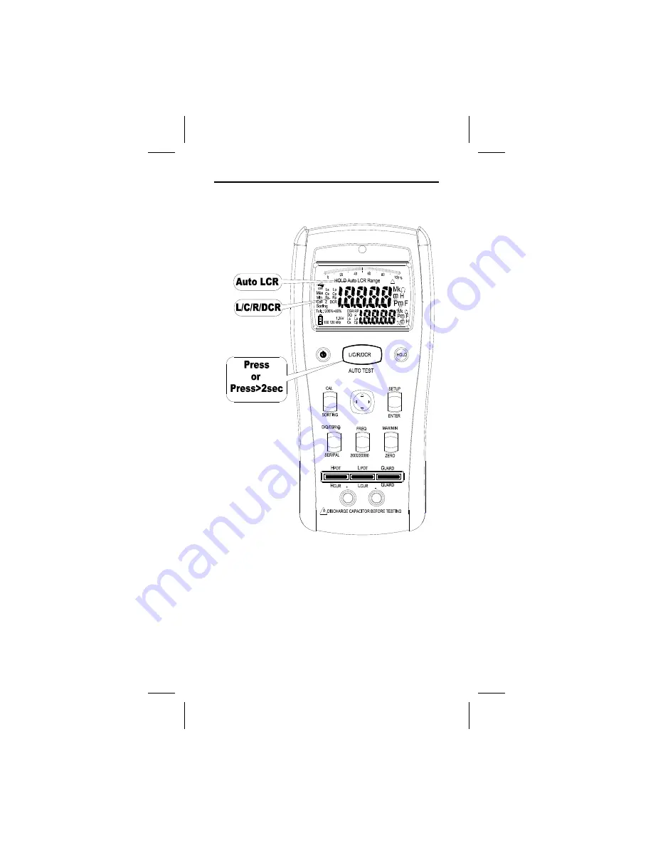
Measuring L/C/R/DCR


• Press the L/C/R/DCR button to select the measuring function. 
• Press the L/C/R/DCR button for 2 seconds to enter the Auto  
   L/C/R function.


Summary of Contents for LCR 1701

Page 1: ...EN Instruction Manual LCR 1701 LCR 1703 Digital Multimeter...

Page 2: ...ry door or Meter case Use the Meter only as specified in this manual or the protec tion by the Meter might be impaired Always use proper terminals switch position and range for measurements Do not app...

Page 3: ...t in damage the meter and the equipment under test Do not expose Meter to extremes in temperature or high humidity Symbols as marked on the Meter and Instruction manual Maintenance Do not attempt to r...

Page 4: ...3 The Meter Description Front Panel Illustration 1 LCD display 20000 2000 counts 2 Function buttons 3 5 Wire input terminal for SMD test probe or DIP part 4 2 Wire input terminal for Alligator Clip...

Page 5: ...4 The assembly 1 5V AC Adapter only LCR 1703 2 USB Cable only LCR 1703 3 Shorting Bar 4 SMD Test Probe only LCR 1703 5 Alligator Clip Set...

Page 6: ...5 Measuring Principle tan D 1 Q R X X tan C 1 fC 2 1 X L fL 2 X R X X tan X X R Z X j X R E C L 1 C L C L 1 C L 2 C L Series Measuring Parallel Measuring S S jX R Z P P jX 1 R 1 Y...

Page 7: ...6 Phase Drawing...

Page 8: ...7 Making 5 wire measuring with the SMD test probe...

Page 9: ...8 Making 4 wire measuring in the 5 wire terminal Making 2 wire measuring with the alligator clip set...

Page 10: ...9 Measuring L C R DCR Press the L C R DCR button to select the measuring function Press the L C R DCR button for 2 seconds to enter the Auto L C R function...

Page 11: ...10 Measuring D Q ESR Press the D Q ESR button to select the measuring function...

Page 12: ...11 Select test Frequency Press the FREQ button to select the test frequency The 100KHz test frequency is only at LCR1703...

Page 13: ...12 Select Series Parallel measuring function At the L C R measuring function it defaults to Auto Series Parallel measuring function Press the SER PAL button to select the measuring function...

Page 14: ...ars on the sub display The after input values will subtract the reference value and display on the main display To use the Zero mode follow the steps below 1 Press the Zero button to enter Zero mode T...

Page 15: ...low 1 Press the MAX MIN button to enter the MAX MIN mode The MAX appears on the display the maximum value on the main display and the current value on the sub display 2 Press the MAX MIN button to sel...

Page 16: ...15 Calibrate In order to achieve the best measuring result calibration is must To calibrate the meter press the CAL button...

Page 17: ...st probe open and press the CAL button to start open calibration About 30 seconds later the result of the open calibration appears on the main display If the result is pass press the CAL button to nex...

Page 18: ...short and press the CAL button to start short calibration About 30 seconds later the result of the short calibration appears on the main display If the result is pass press the CAL button to complete...

Page 19: ...18 Sorting To check the accuracy of the part press the SORTING button to enter the sorting mode The sorting result appears on the main display and the current value appears on the sub display...

Page 20: ...o enter the setup mode 2 Press and button to setup the range of the standard value Then press the ENTER button to save the setup value and enter the next step 3 Press and button to setup the standard...

Page 21: ...eries as soon as the low batteries indicator appears to avoid false reading 1 5V x 4 alkaline batteries External Power Source To save the batteries power by using the external power source Caution Use...

Page 22: ...60 C 0 to 80 R H batteries not fitted Temperature Coefficient 0 15 x Spec Accy C 18 C or 28 C Measure Samples 1 25 times per second normal Altitude 6561 7 ft 2000m Weight 630g including battery Dimens...

Page 23: ...e Test Probe 60cm 1MHz 5 Wire Alligator Clip Set 15cm 1kHz 2 Wire Accuracy A x B of reading A Basic Accuracy as specified by B Test Cable Accuracy B 1 L x F x T L m Cable Length F MHz Test Frequency T...

Page 24: ...0 000mH 0 5 5d 2 200 00mH 0 2 5d 2000 0mH 20 000H 200 00H 2000 0H 0 5 5d 20 000KH 1 0 5d 2 1KHz 2000 0uH 0 5 5d 2 20 000mH 0 2 5d 200 00mH 2000 0mH 20 000H 200 00H 0 5 5d 2000 0H 1 0 5d 2 10KHz 200 00...

Page 25: ...0 5 5d 2 2000 0pF 0 2 5d 20 000nF 200 00nF 2000 0nF 0 5 5d 20 000uF 2 0 5d 200 00uF 5 0 5d 2 100KHz 1 20 000pF 0 5 20d 2 200 00pF 0 2 5d 2000 0pF 20 000nF 200 00nF 0 5 5d 2000 0nF 2 0 5d 20 000uF 5 0...

Page 26: ...0 0 5 15d 2 200 00 0 2 5d 2 0000K 20 000K 200 00K 2 0000M 2 0 5d 20 000M 5 0 5d 100KHz 1 20 000 0 5 15d 2 200 00 0 2 5d 2 0000K 20 000K 200 00K 2 0 5d 2 0000M 5 0 5d 1 The 100KHz test frequency is onl...

Page 27: ...00 00 range Measuring Time 2 seconds 2 wire Accuracy Add 1 0 to accuracy 8 D Q Definition Q 1 D Range 2 000 2000 Minimum Resolution 0 001 in the 2 000 range Accuracy Accuracy of Main Reading x 1 D Inp...

Page 28: ...teration contamination or abnormal conditions of operation or handling Any implied warranties arising out of the sale of this product including but not limited to implied warranties of merchantability...

Page 29: ...Road Shanghai 200001 China www rs components com Europe RS Components Ltd PO Box 99 Corby Northants NN17 9RS United Kingdom www rs components com Japan RS Components Ltd West Tower 12th Floor Yokoham...

Reviews: