background image

14

15

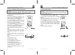
5-13. MAX/MIN
Note:

 When using the MAX/MIN function in Autoranging mode, the meter will “lock” into 

the range that is displayed on the LCD when MAX/MIN is activated. If a MAX/Min reading 
exceeds that range, an “OL” will be displayed. Select the desired range BEFORE entering 
MAX/MIN mode.
1. Press the 

MAX/MIN

 key to activate the MAX/MIN recording mode. The display icon 

"

MAX

" will appear. The meter will display and hold the maximum reading and will update 

only when a new “max” occurs.
2.Press the 

MAX/MIN

 key again and the display icon "

MIN

" will appear. The meter will 

display and hold the minimum reading and will update only when a new “min” occurs.
3.To exit MAX/MIN mode press and hold the 

MAX/MIN

 key for 2 seconds.

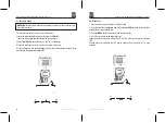
5-14. REL Function

The REL Function allows a reference value measurement to balance possible line losses 
such with resistance measurements or residue magnetism of the current sensor. For this 
purpose, the current indicated value is set to zero. A new reference value is set.
Press the 

REL

 key to activate this measuring function. “REL” appears on the display.

In order to deactivate this function, press the 

REL

 key again and the REL display will 

disappear.

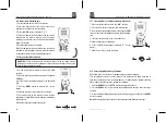
5-15. Display Backlight

Press the 

HOLD

 key for >1 second to turn on or off the display backlight function.

5-16. HOLD

The hold function freezes the reading in the display. Press the 

HOLD

 key momentarily to 

activate or to exit the 

HOLD

 function.

5-17. AUTO Power Off

The auto off feature will turn the meter off after 15 minutes. To disable the auto
power off feature, hold down the MODE button and turn the meter on.

5-18. LOW Battery Indication

The   icon will appear in the lower left conner of the display when the battery voltage 
becomes low. Replace the battery when this appears.

6. Maintenance

WARNING:

 To avoid electric shock, disconnect the test leads from any source of 

voltage before removing the back cover or the battery or fuse covers.

WARNING:

 To avoid electric shock, disconnect the test leads from any source of 

voltage before removing the battery cover.

WARNING:

 To avoid electric shock, do not operate the meter until the battery cover 

is in place and fastened securely.

WARNING:

 To avoid electric shock, do not operate your meter until the battery and 

fuse covers are in place and fastened securely.

This MultiMeter is designed to provide years of dependable service, if the following care 
instructions are performed:
1. 

KEEP THE METER DRY.

 If it gets wet, wipe it off.

2. 

USE AND STORE THE METER IN NORMAL TEMPERATURES.

 Temperature 

    extremes can shorten the life of the electronic parts and distort or melt plastic parts.
3. 

HANDLE THE METER GENTLY AND CAREFULLY.

 Dropping it can damage the 

    electronic parts or the case.
4. 

KEEP THE METER CLEAN.

 Wipe the case occasionally with a damp cloth. DO NOT 

    use chemicals, cleaning solvents, or detergents.
5. 

USE ONLY FRESH BATTERIES OF THE RECOMMENDED SIZE AND TYPE.

    Remove old or weak batteries so they do not leak and damage the unit.
6. 

IF THE METER IS TO BE STORED FOR A LONG PERIOD OF TIME,

 the batteries 

    should be removed to prevent damage to the unit.

6-1. Battery Installation

1. Turn the power off and disconnect the test leads from the meter.
2. Open the rear battery cover by removing the screw using a Phillips head screwdriver.
3. Insert the battery into battery holder, observing the correct polarity.
4. Put the battery cover back in place. Secure with the screw.

NOTE:

 If your meter does not work properly, check the fuses and batteries to make sure 

that they are still good and that they are properly inserted.

Heavy Duty True RMS Digital Multimeter / English

Heavy Duty True RMS Digital Multimeter / English

16/12/2017 Version No. 001

16/12/2017 Version No. 001

Summary of Contents for 161-1626

Page 1: ...d Suite 23 A C East Sea Business Centre Phase 2 No 618 Yan an Eastern Road Shanghai 200001 China www rs components com Europe RS Components Ltd PO Box 99 Corby Northants NN17 9RS United Kingdom www rs...

Page 2: ...symbol indicates a potentially hazardous situation which if not avoided could result in death or serious injury CAUTION This CAUTION symbol indicates a potentially hazardous situation which if not avo...

Page 3: ...for use at the origin of the installation Note Examples include electricity meters and primar y over current protection equipment Safety Instructions This meter has been designed for safe use but must...

Page 4: ...tip to the positive side of The circuit 4 Read the voltage in the display 5 2 AC Voltage Frequency Duty Cycle Measurements WARNING Risk of Electrocution The probe tips may not be long enough to contac...

Page 5: ...cuit Touch the red test probe tip to the positive side of the circuit 5 Read the mV voltage in the display 1 Insert the black test lead banana plug into the negative COM jack 2 For current measurement...

Page 6: ...he red test probe tip to the hot side of the circuit 8 Apply power to the circuit 9 Read the current in the display 10 Press the Hz button to indicate Hz 11 Read the frequency in the display 12 Press...

Page 7: ...nal will sound If the circuit is open the display will indicate OL 5 8 Diode Test 1 Set the function switch to the CAP position 2 Insert the black test lead banana plug into the negative COM jack and...

Page 8: ...rge Wait until the readings settle before ending the test 6 Read the capacitance value in the display 5 11 Frequency Duty Cycle Measurements Electronic 1 Set the rotary function switch to the Hz posit...

Page 9: ...this appears 6 Maintenance WARNING To avoid electric shock disconnect the test leads from any source of voltage before removing the back cover or the battery or fuse covers WARNING To avoid electric s...

Page 10: ...conds max with reduced accuracy All AC Cur rent ranges are specified from 5 of range to 100 of range NOTE Accuracy is stated at 18 C to 28 C 65 F to 83 F and less than 75 RH Function Range Resolution...

Page 11: ...pprox test current 0 35 mA Temperature Sensor Requires type K thermocouple Input Impedance 10 M V dc 10 M V ac AC Response Averaging ACV Bandwidth 45 Hz to 1 kHz Crest Factor 3 at full scale up to 500...

Page 12: ...para evitar lesiones personales o da os en el medidor WARNING El s mbolo de ADVERTENCIA indica una situaci n potencialmente peligrosa que de no evitarse podr a provocar la muerte o lesiones graves CA...

Page 13: ...cluyen medidores de electricidad y equipo primario de protecci n contra sobrecorriente Instrucciones de seguridad Este medidor ha sido dise ado para un uso seguro pero debe ser operado con precauci n...

Page 14: ...la pantalla 5 2 Mediciones de voltaje AC frecuencia ciclo de trabajo ADVERTENCIA Riesgo de electrocuci n Las puntas de las sondas pueden no ser lo suficientemente largas como para entrar en contacto c...

Page 15: ...segundos Exceder los 30 segundos puede da ar el medidor y o los cables de prueba 1 Inserte el conector banana del cable negro de prueba en el enchufe negativo COM 2 Para mediciones de corriente de ha...

Page 16: ...bra el circuito en el punto donde desea medir la corriente 7 Toque la punta de la sonda de prueba negra en el lado neutral del circuito Toque la punta de la sonda de prueba roja en el lado caliente de...

Page 17: ...lla 4 Toque las puntas de la sonda de prueba al circuito o cable que desea verificar 5 Si la resistencia es inferior a aproximadamente 35 sonar la se al audible Si el circuito est abierto la pantalla...

Page 18: ...les cordons sur le condensateur tester 5 Le test peut prendre jusqu 3 minutes ou plus pour charger de grands condensateurs Attendez que les lectures se terminent avant de terminer le test 6 Lire la va...

Page 19: ...ctiver ou quitter la fonction HOLD 5 17 Arr t automatique La fonction d extinction automatique teindra l appareil apr s 15 minutes Pour d sactiver la fonction de mise hors tension automatique maintene...

Page 20: ...de la batterie 3 Retirez d licatement l ancien fusible et installez le nouveau fusible dans le support 4 Utilisez toujours un fusible de taille et de valeur appropri es coup rapide de 0 8 A 1000 V po...

Page 21: ...logique num rique Enferm Double moul imperm able l eau Choc test de chute 6 5 pi 2 m tres Test de Diode Courant de 0 9 mA maximum circuit ouvert tension de 2 8 V cc typique V rification de continuit U...

Page 22: ...s par une double isolation selon EN61010 1 et IEC61010 1 2 me dition 2001 cat gorie IV 600V et Cat gorie III 1000V Degr de pollution 2 Le lecteur respecte galement les normes UL 61010 1 2e dition 2004...

Page 23: ...ein Ger t durch doppelte Isolierung oder verst rkte Isolierung gesch tzt ist 2 Sicherheit Eingabe Schutz Grenzwerte Funktion Maximale Eingabe V DC or V AC 1000 V dc ac rms mA AC DC 800 mA 1000V schnel...

Page 24: ...h Taste 4 Modus Taste 5 Funktion switch 6 MA A und 10A Eingangsbuchsen 7 COM Eingangsbuchse 8 Positive Eingangsbuchse 9 Halten und Hintergrundbeleuchtung Taste 10 Hz und Taste 11 Relativer Geschmack H...

Page 25: ...ive com Buchse Stecken Sie den roten Test Blei Bananenstecker in die positive V Buchse 3 Ber hren Sie die schwarze Pr fspitzen Spitze auf der neutralen Seite des Stromkreises Ber hren Sie die rote Pr...

Page 26: ...sen Sie den Strom auf dem Display 5 5 Wechselstrom Frequenz Einschaltzyklus Messungen VORSICHT Machen Sie 20 A Strommessungen nicht l nger als 30 Sekunden Mehr als 30 Sekunden k nnen das Messger t und...

Page 27: ...n 4 Ber hren Sie die Pr fspitzen ber den zu pr fenden Stromkreis oder Teil Es empfiehlt sich eine Seite des zu pr fenden Teils zu trennen damit der restliche Stromkreis den Widerstand nicht beeintr ch...

Page 28: ...Temperatur Sie messen m chten Halten Sie die Sonde an das zu pr fende Teil bis sich die Messung stabilisiert ca 30 Sekunden 5 Lesen Sie die Temperatur im Display Hinweis der Temperaturf hler ist mit e...

Page 29: ...en wird das Messger t in den Bereich Sperren der auf dem LCD Display angezeigt wird wenn max min aktiviert ist Wenn ein max min Messwert diesen Bereich berschreitet wird ein OL angezeigt W hlen Sie de...

Page 30: ...er einen l ngeren Zeitraum gelagert werden soll sollten die Batterien entfernt werden um Sch den am Ger t zu vermeiden WARNUNG Um einen Stromschlag zu vermeiden trennen Sie die Testleitungen von jeder...

Page 31: ...Genauigkeit Alle AC Strombereiche werden von 5 des Bereichs bis 100 des Bereichs angegeben Hinweis Genauigkeit ist bei 18 c bis 28 c 65 f bis 83 f und weniger als 75 RH angegeben Funktion Bereich Auf...

Page 32: ...ine Indikation f r positiv Minuszeichen f r negative Messgeschwindigkeit 2 Mal pro Sekunde nominal Niedrige Batterieanzeige wird angezeigt wenn die Batteriespannung unter Betriebsspannung sinkt Batter...

Page 33: ...rsonali o danni allo strumento WARNING Questo simbolo di AVVERTENZA indica una situazione potenzialmente pericolosa che se non viene evitata potrebbe provocare la morte o gravi lesioni CAUTION Questo...

Page 34: ...ntatori elettrici e dispositivi di protezione da sovracorrente primaria Istruzioni di sicurezza Questo strumento stato progettato per un uso sicuro ma deve essere utilizzato con cautela Le regole elen...

Page 35: ...one sul display 5 2 Misure di tensione AC frequenza ciclo di lavoro AVVERTIMENTO Rischio di elettrocuzione Le punte delle sonde potrebbero non essere abbastanza lunghe da entrare in contatto con le pa...

Page 36: ...nte da 20 A per pi di 30 secondi Il superamento di 30 secondi pu causare danni allo strumento e o ai puntali 1 Inserire la spina a banana del puntale da test nero nella presa COM negativa 2 Per misura...

Page 37: ...ircuito nel punto in cui si desidera misurare la corrente 7 Tocca la punta della sonda di prova nera sul lato neutro del circuito Toccare la punta della sonda di prova rossa sul lato caldo del circuit...

Page 38: ...lay 4 Toccare i puntali della sonda di test sul circuito o filo che si desidera controllare 5 Se la resistenza inferiore a circa 35 verr emesso il segnale acustico Se il circuito aperto il display ind...

Page 39: ...nF sul display 4 Tocca i puntali del test al condensatore da testare 5 Il test pu richiedere fino a 3 minuti o pi per la carica di grandi condensatori Attendi che le letture si stabilizzino prima di t...

Page 40: ...e la funzione di spegnimento automatico tenere premuto il pulsante MODE e accendere lo strumento 5 18 Indicazione batteria scarica L icona apparir nel connettore in basso a sinistra del display quando...

Page 41: ...ensione e del valore corretti 0 8 A 1000 V colpo rapido per la gamma 600 mA SIBA 70 172 40 10 A 1000 V colpo rapido per la gamma 20 A SIBA 50 199 06 5 Rimontare e fissare il coperchio posteriore la ba...

Page 42: ...di 2 metri Test diodo Corrente di prova di massimo 0 9 mA circuito aperto tensione 2 8 V cc tipica Controllo continuit Il segnale acustico suoner se la resistenza inferiore a 35 circa la corrente di t...

Page 43: ...ti dal doppio isolamento secondo EN61010 1 e IEC61010 1 Seconda Edizione 2001 a Categoria IV 600 V e Categoria III 1000 V Grado di inquinamento 2 Lo strumento soddisfa anche UL 61010 1 2a edizione 200...

Page 44: ...nto reforzado 2 Seguridad L mites de protecci n de entrada Funcion Maximasentradas V DC o V AC 1000 V dc ac rms mA AC DC Fusible de acci n r pida 800 mA 1000 V 10 A A AC DC Fusible de acci n r pida de...

Page 45: ...IN 3 bot n RANGE 4 Bot n de modo 5 funci nInterruptor 6 Tomas de entrada de mA A y 10A 7 Toma de entrada COM 8 Toma de entradapositiva 9 Bot n HOLD y el Bot nBacklight 10 Bot n Hz y el Bot n 11 Bot n...

Page 46: ...onector banana del cable negro de prueba en el enchufe negativo COM Inserte el conector banana del cable rojo de prueba en el conector positivo en V 3 Toque la punta de la sonda de prueba negra en el...

Page 47: ...ito 9 Lee la corriente en la pantalla 5 5 Mediciones de corriente AC frecuencia ciclo de trabajo ADVERTENCIA No realice mediciones de corriente de 20 A durante m s de 30 segundos Exceder los 30 segund...

Page 48: ...e las puntas de la sonda de prueba a trav s del circuito o parte bajo prueba Lo mejor es desconectar un lado de la pieza bajo prueba para que el resto del circuito no interfiera con la lectura de resi...

Page 49: ...temperatura desea medir Mantenga la sonda tocando la parte bajo prueba hasta que la lectura se estabilice aproximadamente 30 segundos 5 Lea la temperatura en la pantalla Nota La sonda de temperatura...

Page 50: ...o autom tico el medidor se fijar en el rango que se muestra en la pantalla LCD cuando se activa MAX MIN Si una lectura MAX MIN excede ese rango se mostrar un OL Seleccione el rango deseado ANTES de in...

Page 51: ...EDIDOR DEBE ALMACENARSE POR UN PER ODO DE TIEMPO LARGO las bater as deben retirarse para evitar da os a la unidad ADVERTENCIA Para evitar descargas el ctricas desconecte los cables de prueba de cualqu...

Page 52: ...a Todos los rangos de corriente alterna se especifican desde el 5 del rango hasta el 100 del rango NOTA La precisi n se establece entre 18 C y 28 C 65 F a 83 F y menos del 75 de HR Funcion Rango Resol...

Page 53: ...Tasa de medici n 2 vecesporsegundo nominal Indicaci n de bater a baja se muestra si el voltaje de la bater a cae por debajo del voltaje de funcionamiento Bateria Una bateriade 9 V NEDA 1604 Fusibles...

Page 54: ......
Reviews: