


Original instructions
7
EN
▪
The charger and battery pack may become warm to
touch while charging. This is a normal condition, and
does not indicate a problem.
▪
To prevent overheating, do not charge battery packs
in direct sunlight in hot weather or near heat sources.
▪
Do not charge inside a box or container of any kind.
The battery must be placed in a well ventilated area
during charging.
▪
When the battery is defective, liquid can escape and
come into contact with adjacent components. Check
any parts concerned. Clean such parts or replace
them, if required.
▪
If the battery pack does not charge properly:
(1) Check current at receptacle by plugging in a lamp
or other appliance.
(2) Move charger and battery pack to a location
where the surrounding air temperature is approxi-
mately 65°F–75°F (18°C–24°C).
(3) If charging problems persist, take or send the tool,
battery pack and charger to your local service
centre.
▪
The battery pack should be recharged when it fails to
produce sufficient power on jobs, which were easily
done previously. DO NOT CONTINUE to use under
these conditions. Follow the charging procedure.
▪
Do not incinerate the battery pack even if it is seriously
damaged or can no longer hold a charge. The battery
pack can explode in a fire.
▪
To facilitate the cooling of the battery pack after use,
avoid placing the charger or battery pack in a warm
environment such as in a metal shed, or an uninsu-
lated trailer.
WaRning:
Never attempt to open the battery
pack for any reason. If the plastic housing of the bat-
tery pack breaks or cracks, return to a service centre
for recycling.
ReaD all Of tHe instRUctiOns in tHe cHaR-
geR sectiOn Of tHis manUal befORe at-
tempting tO cHaRge tHe batteRy pack fOR
yOUR tOOl.
▪
Always use correct RS battery pack (the one supplied
with tool or a replacement pack exactly like it.) Never
install any other battery pack. It will ruin your tool and
may create a hazardous condition.
▪
Charge battery packs only in RS chargers.
▪
Use an environmentally safe disposal unit at a munici-
pal waste disposal centre to dispose of a damaged or
worn out battery.
fitting anD RemOving tHe batteRy pack
To remove the battery from the machine: press the bat-
tery release buttons (7) and take the battery out of the
tool.
WaRning:
Always set the forward/reverse
switch (6) in central position before any work on the
machine e. g. fitting and removing a battery, tool
change, transport, maintenance and storage.
To install the battery: Insert the charged battery (8) into
the opening at the base of the power tool until the battery
is securely latched with a click.
batteRy cHaRging
▪
Insert the plug of the charger in the socket. The green
LED on the charging indicator (9) will start to glow thus
indicating that the charger is in standby state.
▪
Insert the battery (8) in the charger socket (10) consid-
ering the polarity.
▪
A new battery will work properly after five times of
charging and discharging. Charge and discharge a
battery, which is not used for a long time, for two to
three times to function well.
▪
When the battery working time is remarkably short de-
spite full charging, the life of the battery may be over.
Replace the battery immediately.
WaRning:
The battery will be fully charged
after 30 minutes, remove it from the charger after this
time.
charging indication:
▪
The green LED starts to glow upon plugging the
charger in the mains.
▪
The green LED ceases to glow and the red LED lights
up after the battery has been placed in the charger,
thus indicating the beginning of the charging process.
▪
During the charging process the charger and battery
might become warm. This is a normal condition, and
does not indicate a problem.
▪
After completion of charging which takes approxi-
mately 30 min, the red LED ceases to glow and the
green LED lights up.
▪
The charger features thermal overload protection for
the battery. Nevertheless we recommend withdraw-
ing the battery from the charger upon expiring of the
charging time. You may use additionally an electric
timer in order to control the charging time.
tO Obtain tHe best life fOR tHe batteRy
▪
When battery is not in use, keep it away from other
metal objects like paper clips, coins, keys, nails,
screws, or other small metal objects that can make
a connection from one terminal to another. Shorting
the battery terminals together may cause fire or ex-
plosion.
▪
Always unplug the charger when not in use and store
in a dry secure place.
▪
Do not charge battery packs and do not store the
charger in premises where the temperature may drop
under 0ºC or 40ºC.
batteRy state inDicatiOn
The battery state during operation can be checked by
the LED display (4). To actuate the indicator press the
ON/OFF trigger switch (5).
3 = Battery 100% - 60% charged.
2 = Battery 60% - 30% charged.
1 = Battery < 30% charged. It is necessary to recharge
the battery.
The direction of decreasing the charge level indicated by
the LEDs is marked on the housing of the power tool.
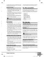
VII - Know your product
Before using the power tool, familiarize yourself with all
operating features and safety requirements.
Use the tool and accessories only for the applications
intended. All other applications are expressly ruled out.
1. Locking sleeve
2. Bit holder
3. LED work light
4. LED battery indicator
5. ON/OFF trigger switch
6. Forward reverse switch
7. Battery release buttons
8. Battery
9. LED charge state indicator
10. Charger
VIII - Operation
leD WORk aRea ligHt
The machine is equipped with LED light (3) to illuminate
the work area and improve visibility when drilling in areas
with insufficient light. The LED light is on until the ON/
OFF switch (5) is pressed.
ReveRsing
The extreme position of lever (6) to the right (viewed from
the rear) is equivalent to anti-clockwise rotation, the ex-
treme position to the left - to clockwise rotation. When
the ON/OFF switch (5) is depressed lever (6) can not be
actuated.
(Fig. 1)
WaRning:
Reversing can be performed only
when the spindle is not rotating!
Drilling and tightening screws are performed with lever
in extreme position to the left. Removal of screws is per-
formed with lever in extreme position to the right.
sWitcHing On - sWitcHing Off
switching on:
press ON/OFF switch (5).
switching off:
release ON/OFF switch (5).
The power tool is equipped with a brake. The spindle
stops rotating immediately after releasing the switch le-
ver.
smOOtH electROnic Rpm cOntROl
Light pressure on ON/OFF trigger switch (5) results in
low rotation speed, further pressing the switch results in
smooth increase of the rpm to maximum upon reaching
the extreme position.
RS-754-1927-pages-GUR 10.8Li.indd 7
8.6.2012 г. 15:14:58 ч.