


4
Guide to Dynamic Balancing V1.09
WWW.RPXTECH.COM
should be completed prior to dynamic balancing. Any dent or chip repair,
painting, or finish treatments should be completed before proceeding.
Reference FAA Advisory Circular 20-37E “Aircraft Propeller Maintenance”
and FAA Advisory Circular 43.13-1B “Acceptable Methods, Techniques, and
Practices - Aircraft Inspection and Repair”Chapter 8.
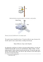
Spinner Installation
Prior to dynamic balancing, the spinner should be removed and inspected.
The spinner should be checked for any mass imbalances caused by foreign
material, missing screws, or damage. The attachment bulkheads should be
inspected for cracks or damage and repaired as required.
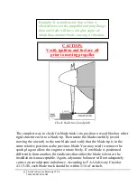
There are instances where spinners have been installed in such a manner as to
allow the front of the spinner to move relative to the propeller. If the spinner
structure has any flexibility, it will move from one side to another at high
RPM, causing the out-of-balance location to shift periodically. The spinner
should be firmly mounted and should not move when laterally loaded.
Blade Track and Pitch
It is important to determine that the blade is tracking correctly. If the blade is
mounted on an irregular surface, if there is debris under the blade, or the blade
is bent it will be impossible to balance the aircraft because the blade will be
aerodynamically out of balance. An aerodynamic imbalance is similar to P-
factor, an asymmetric lift between the blades.
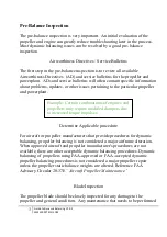
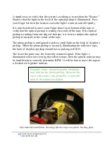
Example: Mud daubers, wasps, and other
insects may nest inside the spinner housing
in only a few weeks.
Summary of Contents for DynaVibe Classic
Page 1: ...DynaVibe Classic User Manual Version 1 09 Aug 2015 WWW RPXTECH COM...
Page 2: ......
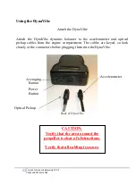
Page 26: ...To download and print this chart please visit WWW RPXTECH COM CHART...
Page 27: ......
Page 28: ...WWW RPXTECH COM...