ROZUM ROBOTICS
PULSE robotic arm
Rev. 6, in effect from Q2 2019
Page
24 | 32
All cables are intact and connected to appropriate connectors.
The emergency stop button is attached to the control box and is located where the operator
can reach it from his/her workplace at any moment.
The operating conditions comply with the requirements as set forth in
Section 1.5
All risks identified during a risk assessment of the operating environment have either been
eliminated or mitigated by implementing appropriate measures (e.g., safeguards, limiting
access to the arm workspace).
There are no obstacles within the workspace of the robotic arm that could prevent the arm
from moving freely or operating properly.
Now, the PULSE arm is ready for switching in accordance with
Section 3.2.
3.2
Switching the arm
To start the PULSE robot, follow the sequence as below:
1.
Plug the power cord of the control box into the mains socket.
2.
Flip the external mains switch (if any) of your system to the ON position.
3.
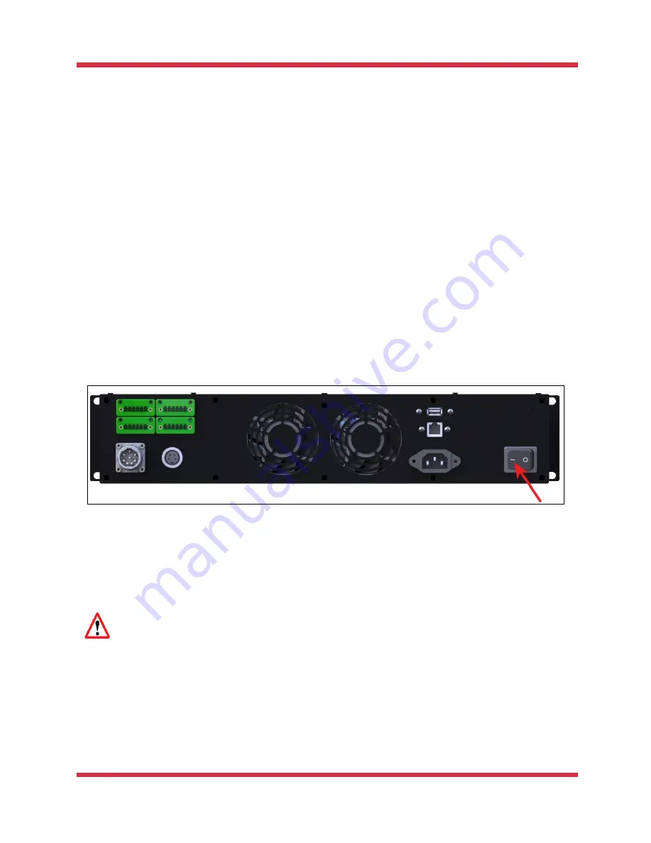
Flip the power switch on the back panel of the control box to the ON position.
The control box starts receiving power and initializing. The green LED on the control box is
blinking, while the LED on the arm wrist is off.
Once the bootup of the control box is over, the green LED goes from blinking to steady green.
Then, the arm starts initializing, too. After the arm initialization is over, the wrist LED turns
steady green, and the arm goes into the READY state.
Do not move the arm until the initialization is over and the wrist LED on the arm is
steady green.
Now, to be able to control your PULSE arm, you need to set up communication between it and a
PC or other control device as detailed in
Section 3.3
3.3
Setting up communication with a PULSE arm
To set communication with a PULSE arm, you can use:
Summary of Contents for PULSE 75
Page 1: ......


