background image

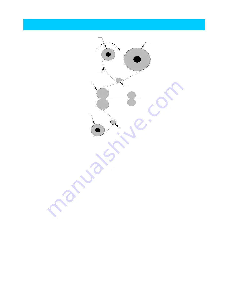
  1. Set up cold film below the upper bar of the machine.

  (Set the same as  methord of the HOT film for protect paper of lower part)

  2. Set the pressure lever to the 15mm, open mode.

  3. Insert a piece of wide cardboard (guiding paper/carrier) between the rollers.

  4. Pull the film from the upper roller passing over the upper idle bar to the upper  roller  and put  it

      on the upper roller.

  5. Put the paper back of the film to the bobbin at take-up bar to rewind   the paper back.

  6. Allow some of the film with melted resin to stick to the Guiding Paper.

  7. Place the film from lower shaft beneath the film from the upper roller which is already  meiting.

     and unwind films of both rollers 30~40cm(1~1.3ft) for loosing  the  tension.

  8. Set the pressure lever to the 1mm.

  9. Set speed at 1 and press the RUN button. The films will be fed into the machine and  will  come

     out from the rear site of machine.

  10. Check the status of lamination and place the pressure lever at lamination mode.   

HANGING   FILM

TAKE UP DEVICE

PAPER BACK

COLD FILM

UPPER IDLE BAR

LOWER IDLE BAR

HOT ROLLER

PAPER BACK


- 7 -

Summary of Contents for 1650C

Page 1: ...Royal Sovereign LAMINATORS OWNER S MANUAL RSC 1650H 1650C PLEASE READ AND SAVE INSTRUCTIONS 1...

Page 2: ...P FILM 6 HANGING FILM 7 CONTROL OF ROLLER PRESSURE 8 INSTRUCTIONS FOR CONTROL PANEL 9 1 FUNCTIONS OF CONTROL PANEL 10 2 HOW TO USE BUTTONS 10 LAMINATING STEPS 11 METHOD FOR USING CUTTER 12 1 CROSS CUT...

Page 3: ...ies scarves papers etc near front or rear machine openings as they could get caught by rollers and be pulled inside causing personal injury 3 Do not insert sharp objects into front or rear machine ope...

Page 4: ...ared Motor 2 Roller Laminating Paper Counting Gross Weight no Dimension W D H mm Unit Weight Gross Demension W D H mm 1960 650 1210 77 2 25 6 47 4 230Kg 500ibs 2100 875 1250 82 7 34 1 49 2 300Kg 660ib...

Page 5: ...OLLER TABLE FRONT UPPER ROLLER X TAKE UP SWITCH PART NAME FRAME GUIDE PAPER RSC 1650H RSC 1650H NAMES OF MAJOR PARTS OF MACHINE CONTROL PANEL FOOT SWITCH ASS Y STAND PRESSURE LEVER TENSION CONTROL KNO...

Page 6: ...ure 1 insert core into the left side of upper lower film shaft 3 Like picture 2 and 3 insert core into the right side of upper lower film 4 Like picture 4 and 5 adhere core closely Make the right left...

Page 7: ...up bar to rewind the paper back 6 Allow some of the film with melted resin to stick to the Guiding Paper 7 Place the film from lower shaft beneath the film from the upper roller which is already meiti...

Page 8: ...inating 15mm thick board RSC 1650H 1650C 3 10 13mm Board For laminating 10 13mm thick board 4 5 7mm Board For laminating 5 7mm thick board 5 1mm Hard Board For laminating 1mm thick board 6 Laminating...

Page 9: ...We designed this machine standing by user s convenience You can manipulate speed and temperature Terms INSTRUCTIONS FOR CONTROL PANEL 6 1 4 2 6 2 1 3 3 5 9...

Page 10: ...e the rollers run backward 2 HOW TO USE BUTTONS Push the button in order to run rollers and push button to stop it SPEED BUTTON Push the SPEED button to increase the speed push the speed button to dec...

Page 11: ...condition 4 After pressing the RUN STOP button choose and set proper speed by using the SPEED button or 5 Turn on the take up device and set the proper film tension by pressing the RUN STOP button Lo...

Page 12: ...ation move cutter to a point about 1 3 of the width of lamination 3 Grasp film with one hand and press the cutter cutter downward and slide it to the direction intending to cut with another hand 4 Pre...

Page 13: ...lted resin will adhere to one roller and ruin future laminations 2 The width of film should be bigger than the material and Width of upper side and lower side of film should be same in order not to al...

Page 14: ...film tension result 6 BOLT CORE 8 Washer 8 6 Bolt M8X12 1 Power cord may not be plugged in 2 Power switch is at OFF mode 3 Emergency switch may be at 1 1 Core 76mm FUSE 50T AC250V 6 3A FUSE 65TS AC25...

Page 15: ...include cleaning or damage caused by accident neglect misuse or improper installation operation or external scratch any damage caused from service maintenance modifications or tampering by anyone oth...

Reviews: