Modbus Option Card Properties
Publication
PUB091-004-00_0918
19 of 64
4
RS-485 DATA HIGHWAY, CONNECTIONS AND MFU SETUP
4.1 Data Highway
The MFU uses RS-485, 2-wire, half duplex, and Modbus RTU communications at various data rates.
The rules governing the installation and connection of an RS-485 highway should be observed at all
times to produce a successful installation. The RS-485 highway does not allow power to be
transferred and the MFU is powered from the actuator itself. The MFU can only report data when the
actuator or electronics module is powered up. (The actuator may have an auxiliary power supply
attached, so that actuator position can be reported even when the main actuator supply is removed).
T
T = Terminator
T
PLC
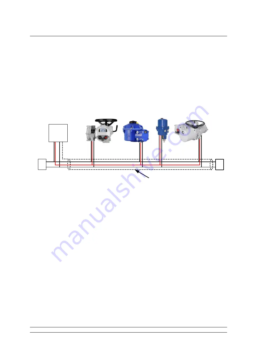
Screened cable throughout
Fig 11:
Typical RS-485 Data Highway
The data highway must be terminated with a resistor of 120 ohms at each end. One of the terminators
must be an active termination. This requires a 5 volt DC power supply. The negative side of the supply
is attached to the data negative wire by a 560 ohms resistor. The positive side of the supply is
attached to the data positive wire by another 560 ohm resistor. Data positive is the wire which has a
positive voltage on it compared to the data negative wire when a logic 1 pulse is on the highway.
The highway itself can use tapped spur or stub connections to the actuators, but it is recommended to
keep any stub lengths to a minimum for successful operation. Alternatively, the connection can be
made in and out of each actuator in a daisy-chain arrangement. The length of the highway and
number of devices connected will vary from project to project. The Modbus standard permits up to 32
devices to be connected per segment, though one of these devices will be the PLC. If more devices
are needed, (up to the maximum addressable of 247) then RS-485 repeaters may be added after each
group of 32. The standard default address of the MFU is 247.
The length of the highway will determine the maximum speed for the data transmission. The greater
lengths are achieved at the lower transmission speeds.
Although RS-485 requires only 2 wires for data transmission, the Modbus standard also requires that
all the nodes on the network have a maximum common mode differential of -7 to +12 volts. This
requires the ground potential at all points to be within the -7 to +12 volt limit. If the equipment is
distributed over a wide area, or an area with poor ground conductivity, it may be necessary to connect
a third wire between all the nodes. Most successful installations use 3 wires and for this, Rotork
provides a ‘common’ terminal on the actuator. The common wire is shown in red above in figure 9.


