5
x
Control unit operation
40
FA ROTEX Solaris RPS3 25M - 03/2010
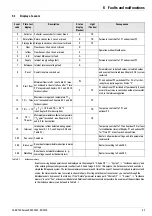
The following notes will help to determine the optimum settings, and guarantee an optimum heat yield with low power
consumption:
•
Adjust the switch-on temperature difference "Delta T On" so that the system remains in operation under constant solar
radiation conditions, and does not switch off immediately when the collector temperature drops due to heat removal. The
lower this value can be adjusted, the longer will be the operating periods with a correspondingly higher heat yield. If the
adjusted switch-on temperature difference is too low, the collector will already cool down so far during filling, that the
switch-off temperature difference is reached.
The circulation pump and, where installed, the booster pump, are switched off again immediately, resulting in low heat
yield with high power consumption.
•
Adjust the switch-off temperature difference "Delta T Off" so that the heat yield obtainable at the switch-off point is higher
than the electrical power required to drive the pump.
Because the power consumption of the pump(s) is virtually independent of the area of the connected collector array
but the available heat output depends directly on the number of solar panels, the parameter value is set higher with
fewer solar panels and lower with more solar panels.
•
The running time "Time P2" of the optional booster pump P2 should be set so that, under all operating conditions, the entire
cross-section of the feed pipe is filled with water. Determine the time required between hearing escaping air when the pumps
are switched on, and water entering the storage tank, and add a safety margin of 20 seconds. The filling period depends on
the adjusted flow rate, the number of collectors, system height, and the length of the connecting pipe.
•
The max. storage tank temperature "T
S
max" is adjusted according to individual requirements. The higher the parameter
value, the higher the heat storage capacity available and, therefore, the potential performance of the Solaris system.
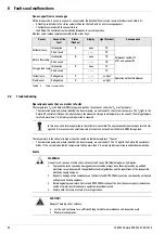
System switch-on involving steam generation can often be disconcerting for the operator. The switch-on inhibit temperature "T
K
perm" is preset at the factory to prevent boiling noises and the escape of steam. The Solaris controller only switches the pump(s)
on again when the collector temperature has fallen 2 Kelvin below the set parameter value. Consequently, the system runs
without evaporation in the collector. However, on a cloudless day, this can lead to a situation where the system only switches
on again in the late afternoon, although the storage tank temperature permits additional heating.
•
For maximum heat yield, the "switch-on inhibit temperature parameter" should be adjusted to a value above 100 °C, which
disables the inhibit function.
In this case, the operator must be informed that there will be considerably more boiling noise and steam hammer during
filling.
5.4.2 Other adjustments of your Solaris system
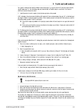
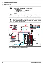
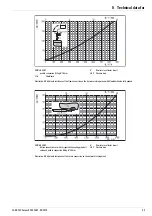
The water flow should be set so that the throughput of every solar panel is 90 to 120 l/h. Adjust the flow rate either by selecting
a speed range for circulation pump P1 and/or by adjusting the FlowGuard (regulating valve with flow rate indicator).
For indirect monitoring of the flow rate, always observe the system temperatures during normal operation. Under optimum solar
radiation conditions (cloudless sky, clear air, sun about vertical to the collector surface), the temperature increase in the collector
should be about 10 to 15 K. During operation with circulation pump P1, for example at a return temperature of 50 °C, set a solar
panel temperature of approximately 60 to 65 °C. If a FlowSensor (FLS) or heat meter is installed on-site, the flow volume can be
set by direct measurement during operation with the pump.
WARNING!
Temperatures over 60 °C can be present in the Solaris DHW storage tank.
•
Install scalding protection.
– e. g. scalding protection VTA 32 (
15 60 15
), k
VS
= 1.6
– Screw fittings set 1" (
15 60 16
)
The reference value for correct valve/pump setting is a nominal flow rate of 100 l/h per solar panel
in the collector array, measured at the FlowGuard (FLG).
In the case of several connected storage tanks, the total nominal flow rate must be split evenly
among the storage tanks.

