background image

AERO W - Air purifier

10

User manual

PART 4.  FILTER AND SENSOR REPLACEMENT

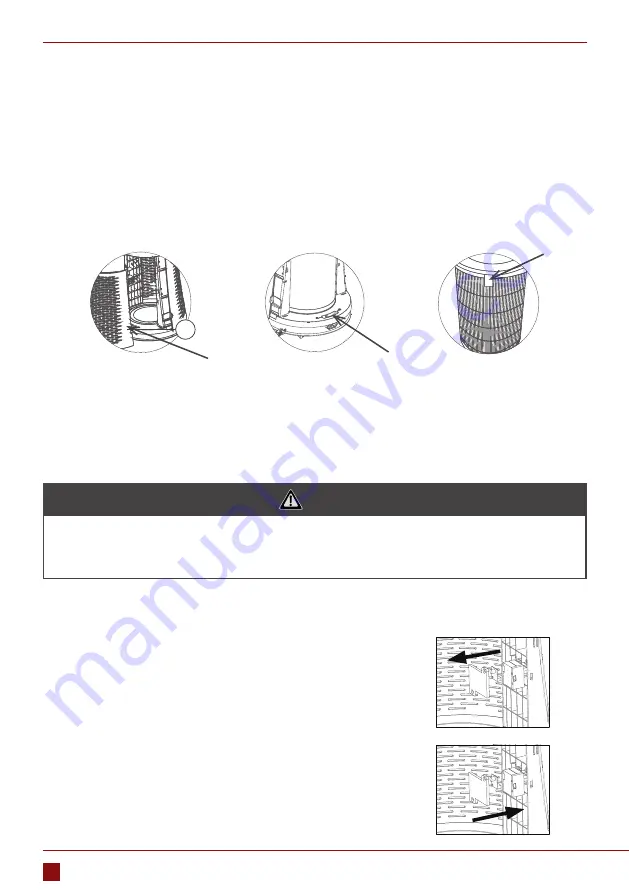
Pic. 4

To replace the filters:

1.  After the purifier power off, hands hold on both sides of the purifier buckle position, open the purifier 

back cover with a little bit harder outward direction. (Pic. 4)

2.  Push the filter lock to the left, unlock the filter fixing device. (Pic. 5)
3.  Pull the cloth tip on the top and end of the filter, take out the filter slowly for replacement (please wrap 

the waste filter in a garbage bag then throw away, to prevent the contaminants from falling into the 
room). (Pic. 6)

1. FILTER REPLACEMENT 

Pic. 5

Pic. 6

4.  Put in a new filter in and move the filter lock towards right side until it is locked, and then put on the back 

cover. (Please identify the correct direction of the filter,the side with cloth tip is for upward and outward).

5.  Turn on power supply, touch “ON/OFF” button to turn on the machine. Keeping touching “FILTER” button 

for 3s to recount the time, keeping touching more than 10s, the services time for filter working will be 
forced to be counted from zero again.


 NOTICE

1.  Please follow the guidance of filter replacement to keep better effect.
2.  The filter to be replaced is not allowed to be used again even it is being cleaned.
3.  Please reset time after replacing the new filter.

To clean/replacement the sensor:

1.  Press “ON/OFF” button to turn off the machine and unplug the 

power plug.

2.  Open the back cover, and take the filter out.
3.  Get out the screws and the sensor protection cover by tool. Take 

out the sensor and take out the connecting wires.(The wire ca-
bles of sensor is small,please take out carefully) (Pic. 7)

4.  Install new sensor and connect cable wires, and fix the 

protection cover by screws again. (Pic. 8)

5.  Take on filter and the back cover.

2. SENSOR CLEANING/REPLACEMENT

Pic

. 8

Pic

. 7

5

Summary of Contents for AERO A60W

Page 1: ...ENG User manual AERO W A60W...

Page 2: ...PART 2 INTRODUCTION 6 Technical Specification 6 Product structure 6 PART 3 OPERATION INSTRUCTIONS 7 Control panel and operation 7 PART 4 FILTER AND SENSOR REPLACEMENT 10 Filter Replacement 10 Sensor c...

Page 3: ...n you can pass the device without the cost B When you buy a new device the seller will accept the old device without any fees C Manufacturer will take the product from buyer produkt without charging i...

Page 4: ...ake off power plug do not let the detective product working 5 This product can only be repaired by authorized repairing center If maintenance in non authorized repair center it is easily lead to other...

Page 5: ...l damage the surface of the machine Only use a soft cloth to clean the surface of the machine otherwise the unit may be damaged or cracked When using this unit do not get near or placed on heat source...

Page 6: ...W D H mm 450 450 915 Weight kg 13 Rated Power W 65 Rated Voltage V Hz 220 240 50 Coverage Area m2 10 120 Noise dB A 68 2 PRODUCT STRUCTURE 1 Controlling Panel 2 Outlet 3 Inlet 4 Decorating Bowl 5 Air...

Page 7: ...standby state 2 8 5 11 7 6 9 10 4 12 3 1 1 ON OFF button Touch ON OFF button to start the machine all buttons lights on control panel will turn on showing in green 2 Digital display area At power on s...

Page 8: ...e automatically adjusted according to the air index 5 ION button Power on state touch this key to start on off negative ion function purifier boot the default negative ion function 6 FILTER button Whe...

Page 9: ...anel is ascended which is convenient for the decorative basin to be cleaned Touch the key again to let the control board down PRECAUTIONS 1 Do not place the purifier in an unstable place 2 Do not pour...

Page 10: ...is for upward and outward 5 Turn on power supply touch ON OFF button to turn on the machine Keeping touching FILTER button for 3s to recount the time keeping touching more than 10s the services time f...

Page 11: ...to replace the filter But due to the actual application of different levels of pollution the use of filter life cycle will be different according to the size of the machine to produce sound and smell...

Page 12: ...l PART 6 ELECTRICAL SCHEMATIC DIAGRAM CN1 CN4 CN6 CN3 CN2 CN1 CN14 CN12 CN13 CN10 CN11 CN5 CN9 CN8 CN3 LED strip light Sensor Magnetic spring switch Anion Motor Stepper motor Operating area control pa...

Page 13: ...due to the entry of dirty outside air 3 The machine is placed in a small place or near obstacles affecting the purification effect 4 The filter dirty affecting the purification effect clean or replac...

Page 14: ...NOTES...

Page 15: ...NOTES...

Page 16: ...www rotenso com email info rotenso com Installer stamp...

Reviews: