background image

Element 50 Manual 

Original Instructions 

Aug 2016 


5) OPERATIONAL SAFETY PROCEDURES


READ BEFORE USING THE MACHINE 


When using electrical tools, basic safety precautions should always be followed to reduce the risk of electric shock, fire and 
personal injury. 


Ensure the magnet is off before plugging in the machine.  


Do not use in wet or damp conditions. Failure to do so may result in personal injury. 


Do not use in the presence of flammable liquids, gases or in high risk environments. Failure to do so may result in personal 
injury. 


Before activating the machine, inspect all electrical supply cables (including extension leads) and replace if damaged. Do not 
use if there are any signs of damage.  


Only use extension cables approved for site conditions. 


Before activating the machine, always check the correct function of all operational systems, switches, magnet etc. 


Before operating, the machine must be securely restrained to a fixed independent feature by using safety strap RDC4083 and 
stationary rings RDC4082. Affix the stationary rings into the magnet, uppermost side hole to reduce the potential free 
movement. Should the magnet become detached from the work piece. Failure to do so may result in personal injury. 


Always wear approved eye protectors, ear defenders and recommended PPE when operating the machine.  


Disconnect from power source when changing cutters or working on the machine.  


Cutters and swarf are sharp, always ensure that hands are adequately protected when changing cutters or removing swarf. 
Use a tool or brush where necessary to remove any swarf or the cutter from the arbor.  


Before operating the machine, always ensure cutter-retaining screws are secured tightly.  


Regularly clear the work area and machine of swarf and dirt, paying particular attention to the underside of the magnet base.  


Always remove tie, rings, watches and any loose adornments that might entangle with the rotating machinery before 
operating.  


Always ensure that long hair is securely enclosed by an approved restraint before operating the machine. 


Should the cutter become stuck in the work piece, stop the motor immediately to prevent personal injury.  Disconnect from 
power source and turn arbor to and fro.  Do not attempt to free the cutter by switching the motor on and off. Wear safety 
gloves to remove the cutter from the arbor.  


If the machine is accidentally dropped, always thoroughly examine the machine for signs of damage and check that it functions 
correctly before resuming drilling.  


Regularly inspect the machine and check for any damaged or loose parts.   


Always ensure when using the machine in an inverted position that only the minimum amount of coolant is used and that care 
is taken to ensure that coolant does not enter the motor unit.  


Cutting tools may shatter, always position the guard over the cutter before activating the machine. Failure to do so may result 
in personal injury. 


 On completion of the cut, a slug will be ejected. 


 When not in use always store the machine in a safe and secure location. 


Always ensure that approved ROTABROACH™ agents conduct repairs.


6) OPERATING INSTRUCTIONS 


Keep the inside of the cutter clear of swarf.  It restricts the operating depth of the cutter.


Ensure that the coolant bottle contains sufficient cutting oil to complete the required operating duration. Refill as required.


Occasionally depress the pilot to ensure cutting fluid is being correctly metered.


To start the machine, follow the control panel operation instructions. The Element machine is fitted with a dual motor 
protection system to fully ensure safety and extended life of the motor. The CutSmart protection (found on the control panel) 
gives a clear and visible indication to the user of torque being applied to the motor, once the prescribed level is reached the 
motor is protected by automatic cut out. To re-start your machine, the operator will simply press the start button again (blue 
tapping button should a protection mode occur during tapping). If, however the speed controller protection is activated, this is 
torque sensor regulated at a pre-determined value above CutSmart (should CutSmart fail to operate) the operator is required 
to press the start button twice to re-activate the machine. 


Always switch off the motor by depressing the green start/stop button or blue button depending upon operation.  Do not 
switch off the motor by pressing the magnet switch.


Apply light pressure when commencing the cut of a hole until the cutter is introduced into the work surface.  Pressure can 
then be increased sufficiently to load the motor. Excessive pressure is undesirable, it does not increase the speed of 
penetration and will cause the safety overload protection device to stop the motor (the motor can be restarted by operating 
the motor start button) and may cause excessive heat which may result in inconsistent slug ejection


Always ensure that the slug has been ejected from the previous hole before commencing to cut the next.


If the slug sticks in the cutter, move the machine to a flat surface, switch on the magnet and gently bring the cutter down to 
make contact with the surface.  This will usually straighten a cocked slug and allow it to eject normally. 


Apply a small amount of light oil lubricant regularly to the slide. 


Cutter breakage is usually caused by insecure anchorage or a loosely fitting slide (Refer to routine maintenance instructions). 


Only use approved cutting fluid. Rotabroach cutting fluid has been specially formulated to maximise the cutters performance.  

Summary of Contents for Element 50/1T

Page 1: ...r Element 50 1T Element 50 3T This machine Serial Number is CE approved Rotabroach Ltd Burgess Road Sheffield South Yorkshire United Kingdom S9 3WD Tel 44 0 114 2212 510 Fax 44 0 114 2212 563 Email info rotabroach co uk Website www rotabroach co uk ...

Page 2: ...nual Original Instructions Aug 2016 2 Thank you for purchasing our Element 50 magnetic drill We would really like your feedback on the machine Other products by Rotabroach Thank you for your purchase of our product ...

Page 3: ...edies for hole making problems 12 15 Wiring diagram 13 16 Exploded view of machine 15 17 Exploded view of motor and gearbox 18 18 Control panel parts and list 21 19 Pipe adapter kit RD2311 22 20 Fitting the chuck 23 21 Maintenance 23 22 Trouble shooting 25 23 Cutter selection and speeds 26 24 Warranty statement 27 P N List of Contents with Magnetic Drill Unit RDC4082 Stationary ring RDC4083 Safety...

Page 4: ...rom the work area 6 Store idle tools when not in use All tools should be stored in a dry locked up place out of reach of children 7 Do not apply too much force through the machine It will do a better and safer job at the feeds for which it was designed 8 Use the right tool Do not force small tools to do the job of a heavy duty tool Do not use this tool for purposes not intended e g do not use the ...

Page 5: ...y and perform its intended function Check for alignment of moving parts binding of moving parts breakage of parts mounting and any other conditions that may affect its operation A guard or other part that is damaged should be properly repaired or replaced by an authorized service centre unless otherwise indicated in this instruction manual Have defective switches replaced by authorized service cen...

Page 6: ... dB A Uncertainty K 3dB A Sound pressure LpA 86 0 dB A Acoustic power LwA 99 0 dB A Uncertainty K 3dB A Ear and eye defenders must be worn when operating this machine Wear gloves to protect hands when operating the machine The declared vibration total value has been measured in accordance with a standard test method and may be used for comparing one tool with another The declared vibration total v...

Page 7: ...of coolant is used and that care is taken to ensure that coolant does not enter the motor unit Cutting tools may shatter always position the guard over the cutter before activating the machine Failure to do so may result in personal injury On completion of the cut a slug will be ejected When not in use always store the machine in a safe and secure location Always ensure that approved ROTABROACH ag...

Page 8: ...ck to the green zone Red Zone Overload Back off immediately as too much force will cause the motor to cut off if you continue CutSmart Technology Designed for you to get the most out of your machine and your cutters CutSmart has an easy to read panel that indicates when you are drilling with too much force which will damage the machine and the cutters Allow the cutter to do the work and you will f...

Page 9: ...ecommended for the drill size being used 4 Turn the motor on in the forward direction 4 5 Drill the hole to the recommended tapping size for the thread to be cut 6 Without disengaging the magnet replace the drill with the tap 7 Set the spindle speed to the required tapping speed required 8 Start the drill spindle in the forward direction 4 and feed the tap into the hole until it begins to cut Once...

Page 10: ... min 265 min 10 MAGNET DETECTION It is advised that when working on thin material a packing piece should be used to increase the material thickness under the magnet Working on thin material without a packing piece will reduce the magnet holding force It is advised that the drill is to be operated on ferrous material 12mm thick and above Damage to the magnet base such as pitting will affect the str...

Page 11: ... CUTTERS 12 MOUNTING OF CUTTERS The machine has been made to accept cutters having 19 05mm 3 4 dia Weldon shanks The following procedure is to be used when mounting cutters With the machine in the upright position ensure the Arbor Assembly CA120 is fully inserted into Arbor Spindle RDC4009 Take appropriate pilot and place through the hole in cutter shank Insert shank of cutter into bore of Arbor A...

Page 12: ... parts Replace part or parts Adjust where necessary 3 Excessive drilling pressure required Incorrectly re sharpened worn or chipped cutter Coming down on swarf lying on surface of work piece Gib strips out of adjustment or lack of lubrication Swarf accumulated packed inside cutter Re sharpen or replace Take care not to start a cut on swarf Adjust setscrews and lubricate Clear cutter 4 Excessive cu...

Page 13: ...ut Brown 2 Speed controller module Lead wire White 3 Speed controller module Lead wire Red 4 Mains Neutral Input Blue 5 Magnet Positive Output 230V Red 110V Blue 6 Magnet Negative Output Black 7 Field coil Lead wire Blue 8 Field coil Lead wire Green 9 Carbon brush Lead wire Black 10 Carbon brush Lead wire Brown ...

Page 14: ... D Motor Forward Switch 5V White E Magnet Switch 0V White F Magnet Switch 5V White G Magnet ON LED 5V White Green H Magnet ON LED 5V White Red I Magnet ON LED 0V White Brown J Power ON LED 0V White Black K Power ON LED 5V White Brown L Motor Reverse LED 0V BLUE White M Motor Reverse LED 12V BLUE White N Motor Forward LED 0V Green White O Motor Forward LED 12V Green White ...

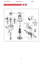
Page 15: ...Element 50 Manual Original Instructions Aug 2016 15 16 EXPLODED VIEW OF MACHINE ...

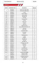
Page 16: ...RDC4055 Screw 2 12 RDA4005 Cable bush 1 13 RDC4056 Screw 4 14 RDC4057 Nut 4 15 RDA4021 Screw M4 8 Button Head 14 16 RDC4058 Right side plate 1 17 RD4098 Screw M6 20 CAP HD 1 18 RDA4029 Screw M6 16 CAP HD 2 19 RDC4104 Spring washer 2 20 RDA3092 Bush 2 21 RDA4006 Capstan Washer 2 22 RDA4004 Circlip 2 23 RDC4059 Screw 10 24 RDC4060 Guide bar 2 25 RDC4061 Slide 1 26 RDC4062 Rack 1 27 RDC4063 Screw 6 2...

Page 17: ... 45 RDC4071 Left side panel 1 46 RD4069 Washer 1 47 RDC4073 Screw 2 48 RDC4074 Cable plug assembly 230V 1 RDC4075 Cable plug assembly 110V 1 49 RDC4076 Control panel assembly E50 3T 1 RDC4077 Control panel assembly E50 1T 1 50 RDC4080 Tapping screw ST2 9 12 using 110V 3 51 RDC4081 Clamp using 110V 1 52 RDC4082 Stationary ring 2 53 RDC4083 Safety belt 1 54 RD4152 3mm hexagonal spanner 1 55 RDC4084 ...

Page 18: ...Element 50 Manual Original Instructions Aug 2016 18 17 EXPLODED VIEW OF MOTOR AND GEARBOX ...

Page 19: ...er 10mm ID 1 8 13 RDB3048 Key steel 1 8 14 RDB3046 Gear axel 1 8 15 RDB2010 Gear lever shaft 1 8 16 RDB2022 Dual gear 1 8 17 RDB4002 Washer 2 8 18 RDC4016 Needle bearing 2 8 19 RDC4017 Circlip 1 8 20 RDC4018 Big gear 1 8 21 RDC4019 Roll Bearing 1 8 22 RDC4020 Oil seal 1 8 23 RD45614 Straight Pin 1 8 24 RM17134 Rolling bearing 608 1 8 25 RDC4021 Shaft gear 1 8 26 RDC4022 Flat Key 1 8 27 RDC4023 Gea...

Page 20: ... Carbon brush 110V 2 8 45 RD33614 Brush holder 2 8 46 RDC4040 Lead wire 1 8 47 RD35617 Terminal 6 8 48 RD45613 Screw M3 6 Button Head 12 8 49 RDC4041 Speed controller module 230V 1 RDC4042 Speed controller module 110V 1 8 50 RDA4035 Tapping Screw 2 8 51 RDC4043 Top Cap 1 8 52 RDC4044 Tapping Screw 4 8 53 RDA4034 Tapping Screw ST2 9 8 4 8 54 RDC4045 Outlet clamp 1 8 55 RDC4046 Plastic tube 1 8 56 R...

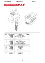
Page 21: ... 1 3 RDC4091 Magnet Switch 1 4 RDC4092 Red LED 1 5 RDC4093 Green LED 1 6 RDA4036 Screw M3 12 BTTN HD 2 7 RDC4094 Control Panel Cover 1 8 RDC4095 Control Plate 230V Tapping 1 RDC4096 Control Plate 110V Tapping 1 9 RDA4019 Nylon Spacer 2 10 RDC4099 Array Board 1 11 RDA4205 M3 Nut 2 12 RDC4100 Connection line 1 13 RDC4101 Connection line 1 14 RDC4103 3 E50PCBA 230V 1 RDC4103 1 E50PCBA 110V 1 ...

Page 22: ...ing care that the magnet is in line with the longitudinal axis of the pipe Switch on the magnet and move the sliding plates down to the outside diameter of the pipe Tighten the screws on both sides by hand then check once again that the full length of the moving plates is touching the pipe at the front and back fasten the plate securely Feed the safety strap through the lugs at the front of the ho...

Page 23: ... that the power supply is disconnected Description Every operation 1 week 1 Month Visual check of machine for damage X Operation of machine X Check brush wear X Check magnetic base X Check alignment of the machine X Check grease X Check armature X Visually check the machine for damage The machine must be checked before operation for any signs of damage that will affect the operation of the machine...

Page 24: ...movement and make any further necessary adjustments Try to ensure that all the screws are exerting a uniform pressure on the slide from top to bottom A perfectly adjusted slide will operate freely up and down without any sideways movement 5 Now raise the slide to its highest position Slightly undo the arbor bearing bracket and using fingers only tighten the screws 6 Place the machine on a steel pl...

Page 25: ...ring bottom of the armature worn out Gear s worn out No grease in gear box Motor humming big sparks and motor has no force Armature damaged Field burned Carbon brushes worn out Motor does not start or fails Damaged or defective wiring Damage to armature or field coil Damaged or defective brushes Guiding takes a great deal of effort Guide is set too tight Guide is dry Guide gear rack rotation syste...

Page 26: ... Plate and sheet steel 900N mm SRCV or SRCVL Aluminium 900Nmm RAP or RAPL Aluminium 900N mm SRCV or SRCVL Brass 900N mm RAP or RAPL Brass 900N mm SRCV or SRCVL Cast iron 900N mm RAP or RAPL Cast iron 900N mm SRCV or SRCVL Stainless steel 900N mm RAP or RAPL Stainless steel 900N mm SRCV or SRCVL Stainless steel 1400N mm CWC to CWCX Rail track 1400N mm SCRWC or SCRWCL Tool steel 1400N mm CWC to CWCX...

Page 27: ...ent servicing or maintenance 3 Defects caused by using accessories components or spare parts other than original Rotabroach parts 4 Tools to which changes or additions have been made 5 Electrical components are subject to manufacturer s warranty Your online registration can be submitted at www rotabroach co uk The warranty claim must be logged within the warranty period This requires the submissio...

Reviews: