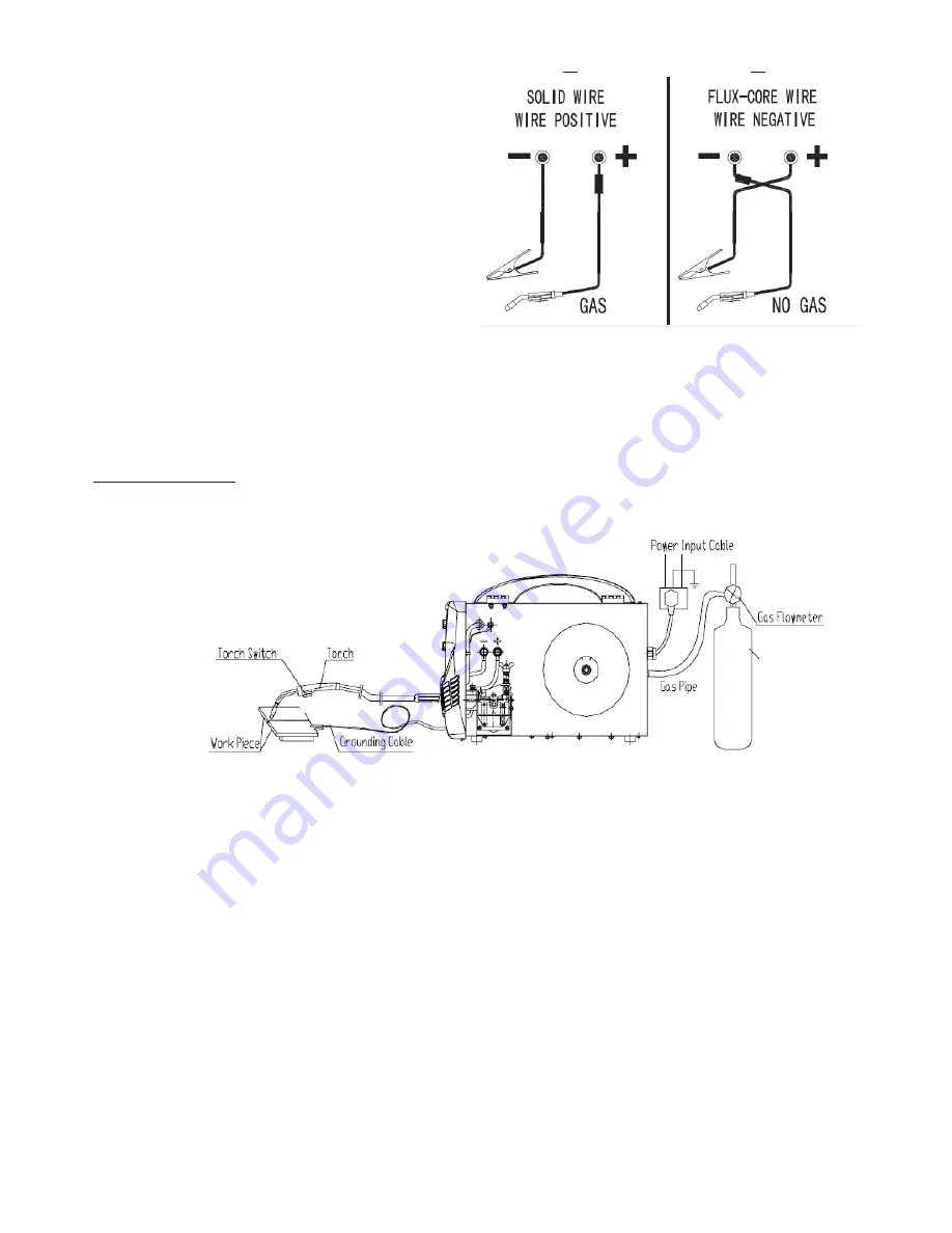
Ross RXT200EX Instructions Manual Download Page 12

POLARITY SELECTION

The  correct polarity must be set for the type of 
welding used. 

When using solid wire  in conjunction  with weld-
ing gas, connect the torch to the positive ter-
minal and the earth clamp to the negative. See 
diagram A. 

When using  flux cored wire (gasless) connect the 
negative terminal to the welding torch and the 
earth clamp to the positive. see diagram B.
Note: The welder MUST be set to manual mode  
for gasless welding using flux cored wire. (see [7] & [8]

CAUTION! 

Check that terminals are tight before commencing to weld to prevent burning

A

B

MIG WELDING

Typical setup

LOADING THE WIRE

•  Open the side cover of the unit 
•  Fit the wire spool onto the spool holder [B] so that the wire will exit the spool from the bottom. Check that 

the spigot fits correctly into the reel.

•  Note the reel holder suits 200 mm reels. 

Adjust the back tension knob [C] as light as possible but sufficiently strong to prevent the wire roll from self 

un-spooling)

•  Fit the torch to the euro fitting and firmly tighten.
•  Release the tension screw [G] and open the upper roller arm [E]
•  Without letting the wire un-spool, cut the end of the wire of cleanly leaving no kinks the feed about 30cm of  

the wire through the guide tube and into the wire liner by hand.

•  The wire feed roller has two different size groves. Check that the wire is aligned with the correct size grove in 

the wire feed roller for the type of wire and then careful close the upper roller and tension screw. If necessary 

remove the wire feed roller and turn it over to access the other grove and refit.

•  At the end of the torch
•  Twist the nozzle clockwise and pull to remove 

Welding Gas

PREPARING FOR MIG WELDING

Summary of Contents for RXT200EX

Page 1: ...l safety information warnings and cautions Failure to comply with instructions could result in personal injury and or damage to product or property Please retain instructions for future reference 200A...

Page 2: ......

Page 3: ...read and understood at all times GENERAL DESCRIPTION A general multipurpose purpose MIG TIG AND MMA welder that fill the needs of most work shops PRODUCT SPECIFICATION Item RXT200EX Input Voltage 230...

Page 4: ...k area with unrestricted movement for the operator Always maintain easy ac cess to the On Off switch and the mains supply THE WORK PIECE The work piece will remain at a high temperature for a relative...

Page 5: ...NG OFF When you have finished welding switch off the welder Do not put the torch down with the welder switch On and with the wire fitted When leaving the welder unattended move the On Off switch to th...

Page 6: ...e piece or on pieces that are connected may generate a dangerous accumulation of no load voltage between two different electrode holders or torches the value of which may reach double the allowed limi...

Page 7: ...ials cleaned with chlorin ated solvents or near such substances Remove all flammable materials e g wood paper rags etc from the working area WARNING Do not weld on containers or piping that contains o...

Page 8: ...upply single phase A C 50 60Hz Regulatory compliance mark Welding Modes MIG MMA TIG Single phase input frequency conversion rectifier X Duty Cycle I2 Welding Current I1max Maximum Input current U2 Wel...

Page 9: ...displays wire feed and set welding voltage It is also used to display gas test gas type and spot time settings See 5 MIG mode with MIG wire size set to manual see 7 8 Displays set wire feed speed and...

Page 10: ...hen set to manual synergic function is disabled and manual wire speed and welding voltage must be set see 5 18 9 Welding wire type switch Use this switch to select the type of welding wire The welder...

Page 11: ...speed Left Right Adjust for the job at hand note The welder will auto matically set the welding voltage based on wire type 9 welding gas 5 and wire size 7 except if manual is selected In MIG mode pre...

Page 12: ...m Check that the spigot fits correctly into the reel Note the reel holder suits 200 mm reels Adjust the back tension knob C as light as possible but sufficiently strong to prevent the wire roll from s...

Page 13: ...asily WARNING The following steps require applying power to the welder Do not touch anything with the torch or wire as it may result in accidental arcing Plug the power cord into its electrical outlet...

Page 14: ...MIG gun has been set up correctly for Aluminium wire Teflon Liner Correct tip for 1 0mm aluminium Check pure argon welding gas is being used is connected and is turned on Fit 1 0mm U grove roller to t...

Page 15: ...to allow the gas to flow WARNING Ensure that you have your protective clothes gloves and welding helmet cor rectly fitted before welding Do not start welding before your eyes are properly protected b...

Page 16: ...an arc all that is necessary to maintain it is to proceed steadily in one direction keeping the gap between the electrode and the work piece constant The electric current will flow through the electr...

Page 17: ...en necessary Daily Check the wear and correct assembly of the consumable parts at the end of the torch swan neck nozzle contact tip Replace when necessary WIRE FEEDER Make frequent checks on the state...

Page 18: ...iner 3 Poor weld penetration Low input voltage Check that if input voltage is the same with rated voltage Bad connection Check grounding ca ble clamp make sure of a good connection Contact tip worn Re...

Page 19: ...NOTES...

Page 20: ...oof of purchase This warranty does not cover defects caused by or resulting from a misuse abuse or neglect b trade professional or hire use c repairs attempted by anyone other than our authorised repa...

Reviews: