


Page 9
RXT150E
ARC WELDING PROCEDURE
Before commencing, make sure that your hand held welding mask or welding helmet is in po-
sition to protect your eyes. It is also advisable to wear gloves and clothing, which cover the
hands and arms to prevent flash burns.
1.
Striking Arc. This is done by bringing the electrode into contact with the work piece us-
ing a light tapping action and withdrawing to create a gap of (1.5 mm – 3.00 mm.).
2.
Maintaining Arc. Having created an arc, all that is necessary to maintain it is to proceed
steadily in one direction keeping the gap between the electrode and the work piece con-
stant. The electric current will flow through the electrode, across the arc gap, and in do-
ing so will melt the electrode core wire and protective flux. The electrode length will
gradually decrease as the metal is transferred to the work piece under a protective slag
formed by the flux. This slag can then be removed when cooled by lightly tapping with a
pointed tool or a welders chipping hammer.
3.
To stop welding, all that is required is to withdraw the electrode from the work piece -
thus breaking the circuit. Be careful with the end of the electrode, as it will be hot! Pro-
vided the current setting is correct, the surface of the work piece will also melt by the
intensity of the electric arc. A degree of “penetration” is thereby obtained and a com-
plete “fusion” of the work piece and the deposited electrodes met
4.
Selection of electrode. There is no hard and fast rule by which a particular gauge of
electrode is selected. Usually this is determined by, the type of weld required and the
thickness of the work piece. E.g. a butt weld in (1.5mm.) sheet metal can be done by a
1.6mm or 2.5mm electrode, the difference being that the 2.5mm electrode will do the
job quicker. The table below Gives guidance as to which electrode is most suitable ac-
cording to the material thickness. This table is only a guide, and values given are an in-
dication only.
Tip!
Keep the welding current as low as possible for the job at hand to maintain the best duty
cycle from you welding machine, prevent the flux from burning and make removal of slag
easier.
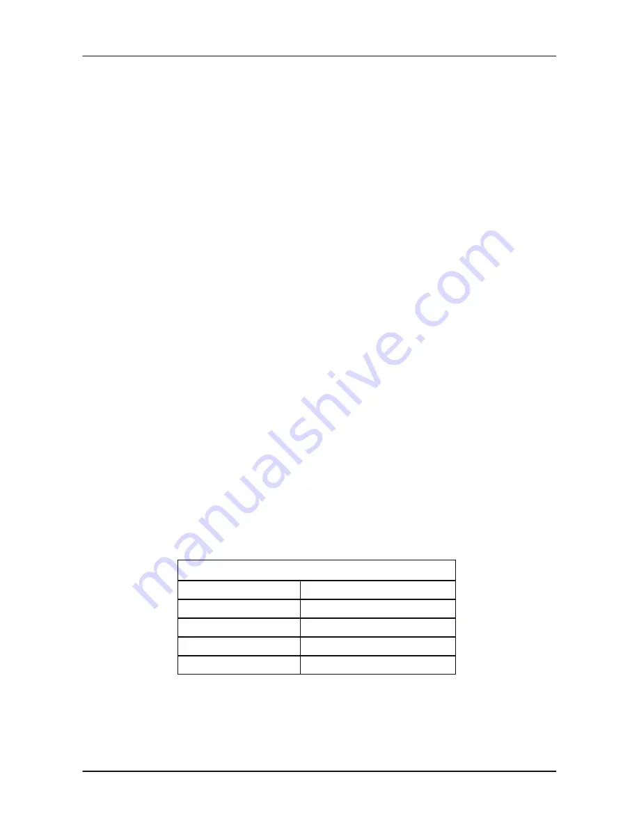
Rod Size Weld
Welding Current
1.6mm
40 - 50 Amps
2.0mm
50 - 75 Amps
2.5mm
75 - 105 Amps
Amperage Selection Guide
3.2mm
105 - 135 Amps


