background image

HDC-8223A(-S) User Manual (Iss. 03)

Installation • 2–5

Cabling Overview

This section provides information for connecting cables to the installed rear modules on the 
openGear frames. Connect the input and output cables according to the following sections. The 
input is internally terminated with 75ohms. It is not necessary to terminate unused outputs. The 
cabling is the same regardless of the card model.

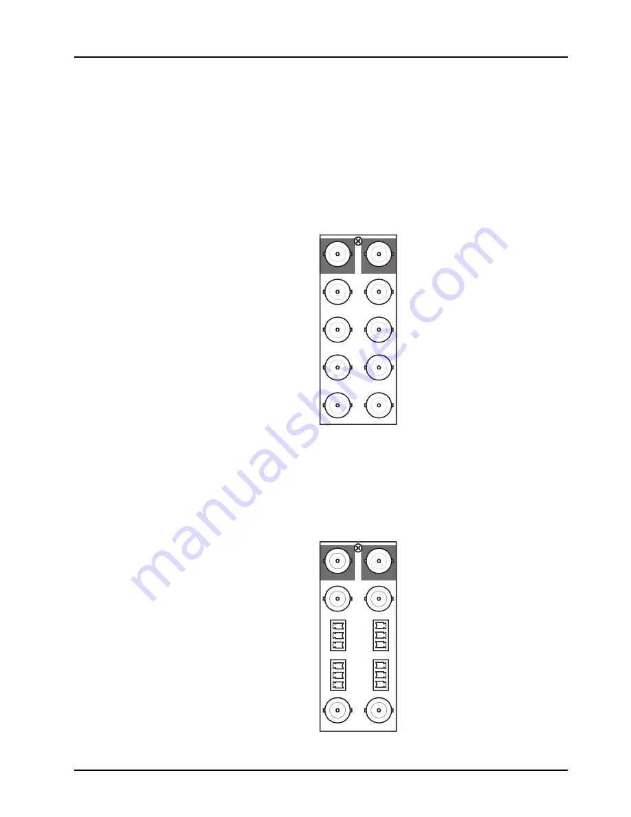
R2-8223A Cabling Overview

Each rear module occupies two slots and accommodates one card. This rear module provides two 
HD/SD-SDI coaxial inputs, four output copies of the re-clocked inputs, and four processed 
coaxial outputs (can be configured as analog composite or SD-SDI). (

Figure 2.2

)


R2C-8223A Cabling Overview

Each rear module occupies two slots and accommodates one card. This rear module provides two 
SDI inputs, two output copies of the re-clocked input, two SDI-Composite outputs, and four 
analog audio outputs. (

Figure 2.3


Figure 2.2  

Cable Connections for the R2-8223A Rear Modules

Figure 2.3  

Cable Connections for the R2C-8223A Rear Modules

1 2

3 4

5 6

7 8
9 10

RCLK Copy

Out 1

SDI In A

RCLK Copy

Out 3

SDI In B

RCLK Copy
Out 2

RCLK Copy
Out 4

SDI/CVBS
Out 2

SDI/CVBS
Out 4

SDI/CVBS

Out 3

SDI/CVBS

Out 1

Card 1

Card 2

SDI In A


RCLK Copy

Out 1

SDI/CVBS

Out 1

SDI In B

RCLK Copy
Out 2

SDI/CVBS
Out 2

Card 1

Card 2

ANLG Audio

Out 1

ANLG Audio

Out 3

ANLG Audio
Out 2

ANLG Audio
Out 4

+

_

G

G

_

+

G

_

+

+

_

G

1 2

3 4

Summary of Contents for OpenGear HDC-8223A

Page 1: ...HDC 8223A S 3G HD Down Converter and Distribution Amplifier User Manual...

Page 2: ...eople that make things happen At Ross our employees are a special group Our employees truly care about doing a great job and delivering a high quality customer experience every day This code of ethics...

Page 3: ...s manual is furnished for informational use only It is subject to change without notice and should not be construed as commitment by Ross Video Limited Ross Video Limited assumes no responsibility or...

Page 4: ...intended for use in areas outside home International This equipment has been tested under the requirements of CISPR 22 2008 or CISPR 32 2015 and found to comply with the limits for a Class A Digital...

Page 5: ...vironmentally friendly and health conscious manner The crossed out wheeled bin symbol invites you to use these systems If you need more information on the collection reuse and recycling systems please...

Page 6: ......

Page 7: ...erms and Conventions 1 8 Installation 2 Before You Begin 2 2 Static Discharge 2 2 Unpacking 2 2 Installing the HDC 8223A S 2 3 Supported Rear Modules 2 3 Installing a Rear Module 2 3 Installing the Ca...

Page 8: ...er Tab 5 11 Framesync Tab 5 12 Closed Captioning Tab 5 15 Video Proc Tab 5 16 Output Audio Routing Controls Tab 5 17 Embedded Output Tab 5 17 Downmixer Tab 5 18 Audio Delay Tab 5 18 Flex Mix Tab 5 19...

Page 9: ...rd of Thanks Congratulations on choosing an openGear HDC 8223A S 3G HD Down Converter and Distribution Amplifier Thank you for joining the group of worldwide satisfied Ross Video customers Should you...

Page 10: ...ing and timecode closed captioning conversion from packet based timecode formats and CEA608 708 HD formats to SD VITC based waveform timecode and line 21 closed captioning available on both SDI and an...

Page 11: ...nput Failover is simple signal presence check only Video Processor The HDC 8223A S provides full color processing control luma gain and lift chroma saturation and color phase of the output video Scale...

Page 12: ...08 containing CEA 608 packets converted to line 21 closed captioning on outputs down converted to SD Timecode Processor As illustrated in Figure 1 1 this function provides for extraction of timecode d...

Page 13: ...e invert control Peak responding DashBoard bar graph level meters are also provided The processor function provides group enable disable and de embedding of the 16 channel embedded audio SDI input A b...

Page 14: ...he R2 8223A full rear module Figure 1 3 Functional Block Diagram R2 8223A Rear Module EQ RECLOCK 3G HD SD SDI In A EQ RECLOCK 3G HD SD SDI In B RCLK Copy 1 RCLK Copy 2 RCLK Copy 3 RCLK Copy 4 DESERIAL...

Page 15: ...SD SDI In A EQ RECLOCK 3G HD SD SDI In B RCLK Copy 1 RCLK Copy 2 DESERIALIZE AUDIO DE EMBED AUDIO ROUTING BULK DELAY OFFSET DOWN MIXER AUDIO DAC ANLG Out 1 ANLG Out 3 ANLG Out 4 ANLG Out 2 VIDEO PROC...

Page 16: ...A with the Frame Sync option enabled OG3 FR series frame refers to the OG3 FR series frames and any available options unless otherwise noted openGear frame refers to the DFR 8321 series and OG3 FR ser...

Page 17: ...n This Chapter This chapter provides instructions for installing the Rear Module s for the HDC 8223A S installing the card into the openGear frame and cabling details The following topics are discusse...

Page 18: ...ng Unpack each card you received from the shipping container and ensure that all items are included If any items are missing or damaged contact your sales representative or Ross Video directly ESD Sus...

Page 19: ...the rear of the frame 2 Remove the Blank Plate from the slot you have chosen for the card installation If there is no Blank Plate installed proceed to the next step 3 Install the bottom of the Rear M...

Page 20: ...n the card edges with the slots in the frame 3 Fully insert the card into the frame until the rear connection plus is properly seated in the Rear Module 4 Verify whether your label is self adhesive by...

Page 21: ...d coaxial outputs can be configured as analog composite or SD SDI Figure 2 2 R2C 8223A Cabling Overview Each rear module occupies two slots and accommodates one card This rear module provides two SDI...

Page 22: ...ure 2 4 Figure 2 4 Connector Wiring for Rear Module Input Sockets 2 Use a tweaker screwdriver to tighten the corresponding capture screw 3 Repeat steps 1 and 2 for each wire on each connector 4 Once t...

Page 23: ...ual Iss 03 User Controls 3 1 User Controls In This Chapter This chapter provides a general overview of the monitoring features available on the card edge The following topics are discussed Control and...

Page 24: ...ble 3 1 LEDs on the HDC 8223A LED Color Display and Description COM Flashing Blue When flashing this LED indicates that the HDC 8223A is receiving control message from DashBoard REF Blue When lit this...

Page 25: ...w of using DashBoard ancillary data line locations and ranges and notes on some of the specific features of the card The following topics are discussed Control and Display Descriptions Using DashBoard...

Page 26: ...view of how navigation is performed between cards function sub menus and parameters Figure 4 1 Function Sub menu Parameter Sub menu Overview HDC 8223A HDC 8223A Submenu A Parameter 1 Parameter 1 Param...

Page 27: ...User Manual should the Tree View not display the card To access a card in DashBoard 1 From the Tree View expand the node for the openGear frame your cards are installed in A list of cards installed i...

Page 28: ...TC 10 Note 2 Dolby Metadata 13 Note 2 13 Note 2 SDI VITC Waveform 14 16 Note 2 Closed Captioning 21 locked 10 Note 2 Notes 1 The card does not check for conflicts on a given line number Make certain t...

Page 29: ...ation within an HD SDI stream Figure 4 3 Example VANC Line Number Allocation Corrected CARD 1 CARD n ATC_VITC 9 8 CC 10 Dolby Metadata 13 CC 10 ATC_VITC 9 8 Dolby Metadata 13 AFD 18 Conflict between A...

Page 30: ...e Priority drop down lists to include ATC_LTC timecode data as a choice This extracts ATC_LTC timecode data from the incoming video Figure 4 7 is an example B of providing both SDI ATC_VITC and VITC w...

Page 31: ...ngs Example Case C In this example even though an ATC_LTC could be available to substitute for ATC_VITC not being present the HDC 8223A will refer to no timecode output since the choice of Disable Out...

Page 32: ...ontained in the packet header to make the determinations listed in Table 4 2 Refer to CEA 708 B for more information Note When receiving HD SDI both CEA 608 and CEA 708 are supported with CEA 608 and...

Page 33: ...ation of the reticule overlay markers to be applied to the output video Sizing and other characteristics for each type of marker can be set Figure 4 11 Typical Reticule Overlay Marker Insertions Overl...

Page 34: ...audio input source to be embedded in the corresponding embedded output channel from the choices in Table 5 13 on page 5 17 Channel Mute Invert and Gain Controls Provides mute and phase invert channel...

Page 35: ...annel content less predominate in the overall mix Audio Delay Controls Delay control adds bulk all four groups audio delay from any video delay net audio delay offset setting adds delay in addition to...

Page 36: ...add a text overlay 1 Select the Character Burner tab 2 Select the Ident 1 sub tab located at the bottom of the Character Burner tab Character Burner Ident 1 Tab 3 From the Overlay menu select one of...

Page 37: ...y Note that the border color is determined by the Character Color setting 10 Click Update to apply your settings 11 Repeat steps 2 to 10 for Ident 2 if you wish to configure a second text overlay Addi...

Page 38: ...xt Box Size menu to configure the dimensions of the overlay If the Text Box Size is set to Custom use the Text Box Width and Text Box Height sliders to adjust the dimensions of the overlay Use the Hor...

Page 39: ...Scaler The Scaler feature provides aspect ratio controls including Horizontal and Vertical pan controls Each Scaler control is fully described in the section Scaler Tab on page 5 11 Figure 4 12 H Pan...

Page 40: ...he file to the card 4 Select the Automatically Reboot After Upgrade box 5 Click Firmware To Load 6 Select the desired upgrade file to be loaded 7 Click Load Selected Firmware 8 The card now reboots an...

Page 41: ...ble from DashBoard for your card Default parameters are noted with an asterisk This chapter contains the following information Status Tabs Timecode Tab Reticules Tabs Input Video Tab Output Video Tab...

Page 42: ...ere FF represents the input video format hh mm ss represents the time since the input changed Errors represents the provided CRC error counter Output Video Reports the current output format SDI Input...

Page 43: ...tion is installed Product Options Indicates which licensed features are installed on the HDC 8223A S Supplier Ross Video Ltd Indicates the provider of the HDC 8223A S Revision Indicates the software v...

Page 44: ...he four supported external formats and internal Free Run in the event the preferred source is unavailable Selects the preferred format to be used in descending order i e Source Priority 2 selects the...

Page 45: ...C waveform is inserted If only one output line is to be used set both controls for the same line number SD VITC Waveform Insertion Enabled Only affects VITC waveform inserted or copied to a new line n...

Page 46: ...zation can only be applied when card is outputting Free Run timecode as reported by the Output Status field displaying Free Run Free Run Seconds If failover to Free Run occurs due to loss of external...

Page 47: ...for card CVBS outputs Any combination of reticules or other markers described below can be inserted Reticule Size Custom Safe Action Area control is customized using the options in this tab SAA Disab...

Page 48: ...ter Height 0 100 Controls height of vertical line percentage of 4 3 outputted image area Center Width 0 100 Controls width of horizontal line percentage of 4 3 outputted image area Horizontal Line Dis...

Page 49: ...B is used If SDI IN A goes valid again failover automatically reverts to SDI IN A Failover B to A Sets main path preference of SDI IN B If SDI IN B goes invalid SDI IN A is used If SDI IN B goes valid...

Page 50: ...of the four coaxial video output connections provides independent selection of setting the port as an SD SDI video output or CVBS analog SD output The output numbers correlate to the output port numb...

Page 51: ...ings Buttons allow standard ARC presets to be applied to output video For any setting using the Horizontal or Vertical controls allow user custom settings Pressing any of the preset buttons restores t...

Page 52: ...rough the frame synchronizer Lock Mode Reference Lock to Input Output video is locked to external reference received on the frame reference bus External reference signal Reference 1 is distributed to...

Page 53: ...t of program input video loss of signal Test Pattern Go to test pattern on program video output in the event of program input video loss of signal The test pattern is defined by the Pattern Select men...

Page 54: ...ed to the output video format selected When using this control be sure to check the Report Delay field to make certain the desired amount of frames are delayed Video Delay read only ms frames lines Sc...

Page 55: ...ing Rejected Due to x Refer to the section Troubleshooting on page 4 8 for details Caption Service is Marked as Inactive Indicates bit in packet from upstream source may inadvertently be set as inacti...

Page 56: ...choose one of the following Yes proceed with the unity reset No reject unity reset Basic Video Proc Luma Gain 0 200 Adjusts gain percentage applied to Luma Y channel Range in 1 steps Unity is at 100...

Page 57: ...on card program video output to accommodate some legacy downstream systems that may not support all four embedded audio groups Disabled Disables this feature Embed Out Ch Embed Out Ch Audio Bus Ch Sel...

Page 58: ...Silence Audio Bus Ch Right Surround Channel Input Silence Audio Bus Ch Center Mix Ratio 80 to 20a a The default value is 0 Adjusts the attenuation ratio of center channel content from 5 channel sourc...

Page 59: ...io input source Source Silence Selects the input source to be directed to the corresponding bus channel Audio Bus Ch Tone Downmixer Mute Mutes the specified channel Gain 80 to 20 Provides relative gai...

Page 60: ...text Type the text to include in the overlay display Update Click this button to apply the changes made to the Display Text field and any options in the tab Character Size Specifies the font size of t...

Page 61: ...xt field Custom Enables you to customize the size of the overlay box using the applicable sliders Text Box Width 0 to 100 When the Text Box Size is set to Custom this slider adjusts the horizontal mar...

Page 62: ...lues as reported by the timecode source HH MM SS Frame The timecode overlay displays the hour minutes seconds and frames value as reported by the timecode source HH MM SS Frame Field The timecode over...

Page 63: ...ay along the Y axis Text Box Size Auto The overlay automatically re sizes to fit the timecode data Custom Enables you to customize the size of the overlay box using the applicable sliders Text Box Wid...

Page 64: ...defined above Layers All Allows selecting a functional layer or area of concern that the preset is concerned with Limiting presets to a layer or area of concern allows for highly specific presets and...

Page 65: ...ation where the preset file was saved to 3 Select the desired file from the provided list 4 Click Open to load the file to the card Load Delete Existing Preset Load Factory Defaults Confirm Allows rec...

Page 66: ...e text in the Display Name field to the standard card name Replace Product Name Replaces the standard card name with the text in the Display Name field Log Status read only Indicates overall card inte...

Page 67: ...us 5 27 Memory Test Restore From SD Card Confirm Do not configure these settings without the guidance of Ross Technical Support FPGA Memory Test Test Memory Test Status read only Table 5 21 Admin Tab...

Page 68: ...me and date of the log file entry Type read only Info Specifies the type of message Warning Event read only Provides a textual description of the log file entry Clear User Log Confirm Clears the five...

Page 69: ...ts remote control interface The HDC 8223A S card requires no periodic maintenance in its normal operation if any error indication occurs use this chapter to correct the condition The following topics...

Page 70: ...indications Depending on how the HDC 8223A S card is being used i e standalone or network controlled through DashBoard check all available indications in the event of an error or failure condition Th...

Page 71: ...connecting to the frame or LAN all controls are grayed out in the Device View right hand side of window Gray indicator icon in Card Access Navigation Tree pane shows card s are not being seen by DashB...

Page 72: ...ther the frame power supply connections or the HDC 8223A S card itself is defective If display shows excessive power being consumed refer to the chapter Specifications on page 7 1 the HDC 8223A S card...

Page 73: ...to appropriate HDC 8223A S video input Make certain BNC cable connections between frame rear module for the HDC 8223A S and signal source are OK The HDC 8223A S shows yellow indicator for input chann...

Page 74: ...etwork Remote Control Errors Should any problem arise with this product that was not solved by the information in this section please contact Ross Video Technical Support Refer to the section Contact...

Page 75: ...ons 7 1 Specifications In This Chapter This chapter provides the technical specification information for the HDC 8223A S Note that specifications are subject to change without notice The following top...

Page 76: ...Return Loss 15dB at 5MHz 270MHz Signal Level 800mV 10 DC Offset 0V 50mV Jitter SD 0 2UI all outputs Overshoot 0 2 of amplitude Pre Processor Reclocked Serial Digital Video Outputs Number of Outputs Fo...

Page 77: ...HDC 8223A S User Manual Iss 03 Service Information 8 1 Service Information In This Chapter This chapter contains the following sections Troubleshooting Checklist Warranty and Repair Policy...

Page 78: ...d the frame and any associated peripheral equipment for signs of trouble 2 Power Check Check the power indicator LED on the distribution frame front panel for the presence of power If the power LED is...

Page 79: ...This User Manual provides all pertinent information for the safe installation and operation of your openGear Product Ross Video policy dictates that all repairs to the HDC 8223A S are to be conducted...

Page 80: ...trade show information Visit Us Visit our website for Company information and news Related products and full product lines Online catalog Testimonials Technical Support Telephone 1 613 652 4886 After...

Reviews: