


DSS-8224 User Guide (v6.0)
Configuration • 25
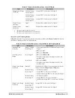
Auto Change Over (ACO) Mode
When in ACO Mode, a Loss of Signal (LOS) or Loss of Lock (LOL) on the primary input will cause the output to
switch to the secondary input. Once the output is switched, the card will check the presence of the primary input to
return. When the primary input has returned for 30 seconds, the output will switch back. DashBoard enables you to
configure the trigger for the ACO Mode when operating in Dual 2x1 mode or Dual 2x1 Tracking mode. If you are
operating in 4x2 or 4x1 modes, the ACO Trigger is automatically set to Loss of Signal. For information on the
available options for the ACO Trigger, refer to the section “
To edit the Auto Change Over Mode, ensure that
JP7
is set to
RCLK
as outlined in the section “
reclocking mode of the DSS-8224
7x1 Mode Setup
This section outlines how to configure the jumpers on the DSS-8224 cards for operating in 7x1 mode, and enabling
the mode on the downstream card. Note that only the downstream, or Master, card is enabled for 7x1 operation.
For More Information on...
• operating in 7x1 mode, refer to the section “
• diagrams illustrating possible 7x1 configurations, refer to
To configure the jumpers on the DSS-8224 cards for 7x1 mode
1. Set
JP1
to
SLAVE
on the upstream DSS-8224 card.
2. Set
JP1
to
MASTER
on the downstream DSS-8224 card.
3. Set
JP3
to
PANEL
on both cards.
4. Set
JP4
to
4x1
on both cards.
5. Set
JP5
to
4 Button
on both cards.
To enable 7x1 mode for the downstream/master card
1. In DashBoard, display the
Device View
of the DSS-8224 by double-clicking its status indicator in the Basic
Tree View.
2. Select the
Setup
tab from the
Device View
.
3. To enable 7x1 mode, select the
7x1 Mode
check box.
Selecting the Timing
The openGear frames accept two external analog references which are distributed to all the cards in the frame.
Either of these references can be used to synchronize the DSS-8224.
The DSS-8224 will switch on the vertical interval when provided with an analog reference. The switching line is
determined via the frame rate (50 or 59.94) and the data rate (SD or HD). The DSS-8224 can switch without an
analog reference, but the switch timing will be random. Use
JP2
and
JP6
in conjunction to configure the switch
timing settings of the DSS-8224.
To configure the switch timing of the DSS-8224
1. Set
JP2
as follows:
•
1080i
— HD video switches at line 7 of the 1080i signal. This is the default setting.
•
720p
— HD video switches at line 7 of the 720p signal.
The 720p switching point is approximately 50 microseconds earlier than the 1080i switching point.
2. Set
JP6
as follows:
•
FRM 1
— Selects the source connected to the
REF 1
port on the back of the frame. This is the default setting.
•
FRM 2
— Selects the source connected to the
REF 2
port on the back of the frame.
Summary of Contents for OpenGear DSS-8224
Page 1: ...DSS 8224 User Guide ...
Page 6: ......
Page 14: ...14 Before You Begin DSS 8224 User Guide v6 0 ...
Page 18: ...18 Hardware Overview DSS 8224 User Guide v6 0 ...
Page 22: ...22 Physical Installation DSS 8224 User Guide v6 0 ...
Page 34: ...34 Software Upgrades DSS 8224 User Guide v6 0 ...
Page 42: ...42 DashBoard Menus DSS 8224 User Guide v6 0 ...
Page 44: ...44 Technical Specifications DSS 8224 User Guide v6 0 ...


