Ross 4800DR-345-02 Installation Manual Download Page 9

Mapping a Single Module • 9

Mapping a Single Module

If you are mapping a single modules to a panel row, you can use select the link and
node that you installed the module on and assign it to a panel row.

1.

Press 

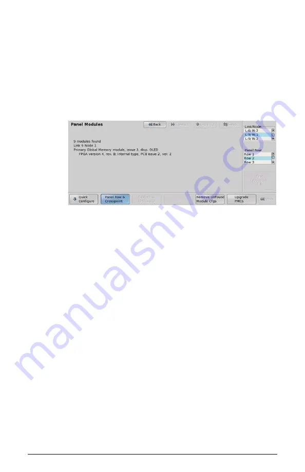
 HOME > More > Setup > More > Panel Modules 

.

A warning is displayed, asking you if you want to enter the menu. Press

Yes

 to display the Panel Modules Menu.

Figure 7: Panel Modules Menu - Panel Row & Crosspoint

2.

Use the 

Link/Node

 knob to select the link and node that the module you

want to assign to a row is installed on. You can also press a button on the
module to go to the link and node.

3.

Press 

Panel Row & Crosspoint

.

4.

Use the 

Panel Row

 knob to select the panel row that you want to assign

the module to. You can select either an internal row (Row 1 to Row 8), or
an external row (Row 1 to Row 16).

5.

Use the 

First Crosspoint

 knob to select the number of the first crosspoint

button on the module you are setting up. Each crosspoint module has 8
buttons, so the first button on module 1 is 1, the first button on module 2 is
9. If the module does not have crosspoint buttons, this knob is gray.

6.

Set up a Custom Control module as follows:

a) Use the 

Link/Node

 knob to select the link and node that the module

you want to assign to a row is installed on. You can also press a button
on the module to jump to the link and node.

b) Press 

Custctrl & GPI Group

.

c) Use the 

First Custctrl

 knob to select the number of the first custom

control button on the module you are setting up. Each custom control
module has 8 buttons, so the first button on module 1 is 1, the first
button on module 2 is 9. If the module does not have custom control
buttons, this knob is gray.

Summary of Contents for 4800DR-345-02

Page 1: ...Ross Video Limited Crosspoint Module Installation Guide V I S I O N...

Page 2: ...ithout notice and should not be construed as commitment by Ross Video Limited Ross Video Limited assumes no responsibility or liability for errors or inaccuracies that may appear in this document Trad...

Page 3: ...rking on circuit boards Environmental Information The equipment that you purchased required the extraction and use of natural resources for its production It may contain hazardous substances that coul...

Page 4: ...If any items are missing or damaged contact Ross Video Technical Support Qty Part Item 1 V 110M Crosspoint Module 1 727 024R Module Control Link Cable Black CAT5e 2 long 1 727 025R Module Control Link...

Page 5: ...nel lid to gain access to the control panel tub 4 Identify the module or blank module plate that you want to remove 5 Disconnect the Module Power Cable from the existing module you want to remove This...

Page 6: ...slot that you want to install the module into 3 Install the four 4 Retaining Nuts located at each corner of the Crosspoint plate to a maximum torque of 5 in lbs 6 cm kg A inch hex driver or wrench is...

Page 7: ...an RJ 45 connector on either end is already installed in the control panel 1 2 Front of Control Panel Module Control Link Cable Figure 4 Module Control Link Cable 2 Connect and secure the free end of...

Page 8: ...e message PMCs need to be upgraded please go to Panel Modules menu is displayed on the Main Menu 1 Press HOME More Setup More Panel Modules A warning is displayed asking you if you want to enter the m...

Page 9: ...ther an internal row Row 1 to Row 8 or an external row Row 1 to Row 16 5 Use the First Crosspoint knob to select the number of the first crosspoint button on the module you are setting up Each crosspo...

Page 10: ...10 Mapping a Single Module Figure 8 Panel Modules Menu Custctrl GPI Group...

Page 11: ...Notes...

Page 12: ...ompany information Related products and full product lines On line catalog News Testimonials PHONE General Business Office and Technical Support 613 652 4886 After Hours Emergency 613 349 0006 Fax 613...

Reviews: