500Mbps Powerline Gigabit Ethernet Adapter KIT
-
RPLC-500KIT
- User
’s Manual
-9-
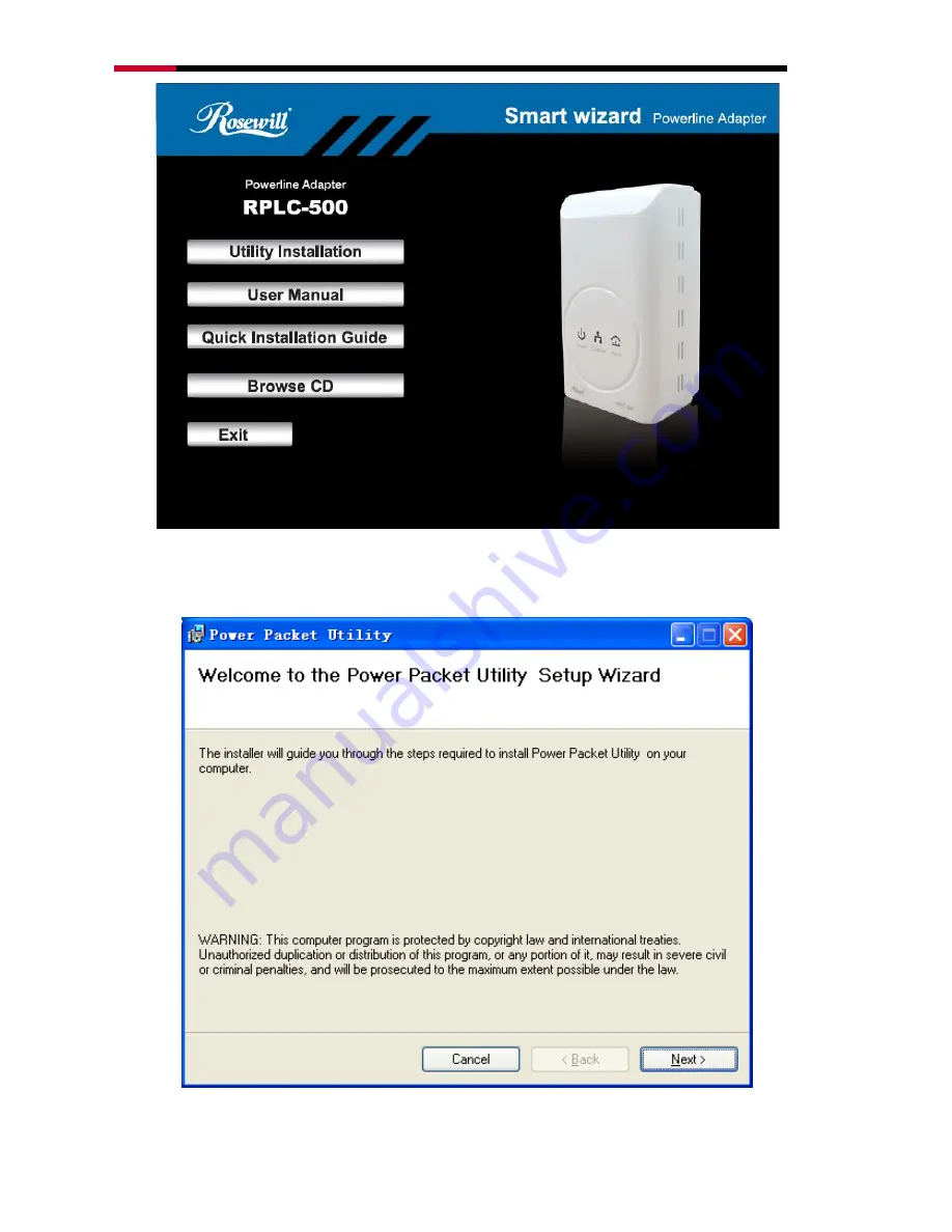
2.
The window for installing the utility software will display. Click
Next
to
continue.
Page 1: ...500Mbps Powerline Gigabit Ethernet Adapter RPLC 500 User Manual...
Page 2: ...7 CHAPTER 2 INTRODUCTION TO UTILITY 8 2 1 UTILITY INSTALLATION 8 2 2 UTILITY INTRODUCTION 12 2 2 1 Main Tab 12 2 2 2 Privacy Tab 15 2 2 3 Diagnostics Tab 16 2 2 4 About Tab 18 CHAPTER 3 FORMING A POW...
Page 3: ...ill RPLC 500 500Mbps Powerline Gigabit Ethernet Adapter 2x RJ45 Ethernet Cable 1x Quick Installation Guide 1x Resource CD for RPLC 500 including Rosewill Powerline Utility Quick Installation Guide Use...
Page 4: ...er outlet in your home with any new cabling Devices can securely communicate with each other via the 128 bit Advanced Encryption Standard AES through RPLC 500 at a high speed transfer rate of 500Mbps...
Page 5: ...ports 4 level type QoS and 8 level VLAN priority fields which automatically improves the streaming quality Green Feature for Power saving mode RPLC 500 will detect signals when there is no signal tran...
Page 6: ...ndows 98SE 2000 ME XP 32 64 bit and Vista 32 64bit otherwise no OS require CPU Intel Pentium III or better clock rate faster than 2 0GHz recommended RAM At least 128MB Screen resolution Any resolution...
Page 7: ...Orange Data Transmit Quality Average Red Data Transmit Quality Poor Off The PLC adapter does not connect to the powerline network 1 5 2 Powerline Adapter s Button and Connector Reset Pressing and hold...
Page 8: ...g into the electrical outlet Chapter 2 Introduction to Utility Note Before installing the PLC utility software make sure that there is no any other powerline utility installed on your computer If ther...
Page 9: ...500Mbps Powerline Gigabit Ethernet Adapter KIT RPLC 500KIT User s Manual 9 2 The window for installing the utility software will display Click Next to continue...
Page 10: ...hernet Adapter KIT RPLC 500KIT User s Manual 10 3 Select I Agree and then Next to continue 4 You can choose your own destination folder to install or click Browse to select the installation folder and...
Page 11: ...Powerline Gigabit Ethernet Adapter KIT RPLC 500KIT User s Manual 11 5 You can choose your own destination folder to install or click Browse to select the installation folder and then click Next to co...
Page 12: ...nnected to the computer when the utility is running The top panel shows the local HomePlugAV devices connected to the network interface card NIC of the computer Click Connect The utility automatically...
Page 13: ...he lower panel Device Name This column shows the default device name which may be modified To change the name click Rename or click the name and edit it in the list MAC Address This column shows the M...
Page 14: ...ering the device password of the device A dialog box will appears You can enter a device name and the password Also refers as DEK on the back Label this DEK is generates via MAC address If the device...
Page 15: ...cluded in the network All HomePlugAV devices are loaded using a default logical network network name which is normally HomePlugAV In the Privacy screen you can modify a private network by changing the...
Page 16: ...network a dialog box appears indicating the success of this operation For the devices whose passwords are not entered this operation will fail and it will report a failure message 2 2 3 Diagnostics Ta...
Page 17: ...networks or devices that no longer exist are shown with a in the rate column The following remote device information is available from the diagnostics screen Device alias name MAC address Password De...
Page 18: ...he software version and provides a html link to a website such as http www qua qualcomm com Clicking the web address you can visit the web site Chapter 3 Forming a Powerline HomePlug AV Network This c...
Page 19: ...2 Press the Security button on Device B for less than 3 seconds The button on B must be pressed within 2 minutes 3 Wait for connection to complete The Power indicator on both devices will flash evenly...
Page 20: ...ion about Device A after connection succeeds Search for Local device on your computer 3 Click the Privacy tab page Enter a name in the Private Network Name field Setting the network name for your PLC...
Page 21: ...evices A and B are located in network N Device C the joiner that is not located in any networks attempts to join Network N Any devices on Network N can become the adder Joining a network Please follow...
Page 22: ...k the Privacy tab page Enter a name in the Private Network Name field 4 Click Set Local Device Only When the page shown as below displayed the setting success Now Device C has been removed from its lo...
Page 23: ...les because it can significantly improve the transmission capacity of the network For the PLC device without female socket it is recommended to plug the device directly into a wall socket not to power...
Page 24: ...ency Band 2 MHz 67 5 MHz Power Consumption 4 0W Operation Mode 2 78W Idle Mode 0 97W Standby Mode QoS Support ToS Support up to 4 level type QoS Support up to 8 level VLAN priority field IGMP snooping...
Page 25: ...Identification NMK Network Membership Key PLC Powerline Communication PIB Parameter Information Block STA Station a STA in the network with a connection to the powerline and being able to source or s...
Page 26: ...GMP default CAP 3 sets the channel access priority for IGMP frames these are the group management frames not the stream data Multicast Broadcast sets the default CAP for multicast frames not in a snoo...
Page 27: ...ear water This product should never be placed near or over a radiator or heat register Do not use an extension cord between the device and the AC power source Only a qualified technician should servic...