Rosewill FBM-06 User Manual Download Page 3

Table of Contents

Thank you for purchasing a 

Rosewill

 Server Chassis. 

Please read the instruction manual before using and 
retain it for your future reference.

1

• Product Overview 

Disassembly Chart 

............................................. 02
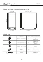
Dimensions 

 ........................................................ 03

Accessory Box 

 ................................................... 03

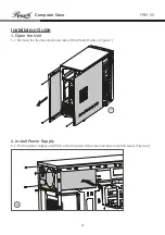
• Installation Guide 

1. Open the Unit 

 ................................................ 04

2. Install Power Supply 

 ...................................... 04

3. Install Motherboard 

........................................ 05

4. Install Add-on Card 

........................................ 05

5. Install 5.25” Drive

 ............................................ 06

6. Install 3.5” Drive

 .............................................. 06

7. Install 2.5” Drive 

 ............................................. 07

8. Care 

 ............................................................... 07

9. Options 

 .......................................................... 07

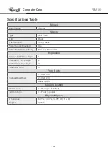
• Specifications Table 

 ........................................... 08

Front I/O Cable Pinout 

 ....................................... 09

Front I/O 

............................................................. 09

Summary of Contents for FBM-06

Page 1: ...Computer Case User Manual FBM 06...

Page 2: ......

Page 3: ...ference 1 Product Overview Disassembly Chart 02 Dimensions 03 Accessory Box 03 Installation Guide 1 Open the Unit 04 2 Install Power Supply 04 3 Install Motherboard 05 4 Install Add on Card 05 5 Insta...

Page 4: ...Computer Case 2 FBM 06 Product Overview Disassembly Chart Components vary by country Front Panel Cooling Fan Left Side Panel Right Side Panel...

Page 5: ...Box Front View Right Side View 173 mm 375 mm 366 mm Image Part Name Q ty Function Component Screw A 6 32 x 6 mm 6 PSU Add on Card Screw B M3 x 5 mm 12 Motherboard 5 25 Drive 2 5 Drive Screw C 6 32 x 5...

Page 6: ...Open the Unit 2 Install Power Supply Installation Guide 1 1 Remove the thumb screws and take off the Panel R and L Figure 1 2 1 Put the power supply unit PSU at the top rear of the case and secure wi...

Page 7: ...M 06 3 Install Motherboard 4 Install Add on Card 3 1 Secure the motherboard down with Screw B Figure 3 4 1 Bend to remove the slot covers Figure 4a 4 2 Install the add on card and secure with Screw A...

Page 8: ...Pull from the bottom of the front panel to remove the panel Push the slot cover out to make room for the drive bay 5 2 Put back the front panel and secure the 5 25 drive with Screw B Figure 5b 6 1 Pu...

Page 9: ...rew B Figure 7a 7b 7c 7d To prevent damage keep all panels closed and secured 8 1 Put the side panels back in place and secure with thumb screws 9 1 Additional Fan Installation The FBM 06 features amp...

Page 10: ...ITX Micro ATX Expansion External 5 25 Drive Bays 1 Internal 3 5 Drive Bays 2 Internal 2 5 Drive Bays 2 Expansion Slots 4 Front Ports Internal Drive Bays 1 x USB 3 0 2 x USB 2 0 Audio In Out Cooling S...

Page 11: ...9 Computer Case FBM 06 Front I O Cable Pinout Front I O Diagram Power USB 2 0 USB 3 0 Reset Mic Speaker USB 2 0 USB 3 0 CONNECTOR USB 2 0 CONNECTOR HD AUDIO CONNECTOR...

Page 12: ...pport Information techsupport rosewill com 1 800 575 9885 Thank you for purchasing a quality Rosewill product Please register your product at www rosewill com for complete warranty information and sup...

Reviews: