POWER SUPPLY
User’s Manual
CAPSTONE-450
CAPSTONE-550
CAPSTONE-650
CAPSTONE-750
GOLD
POWER SUPPLY
All rights reserved by Rosewill
1
Contents
Features
Input & Ouput Rating
Package Content
Connector
Caution
Installation
P. 2
P. 3
P. 3
P. 3
P. 4
P. 5
Easy Trouble Shooting
Information
P. 5
P. 2
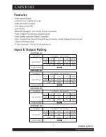
Features
2
• ATX12V v2.31 & EPS12V v2.92
• 80PLUS GOLD Certified
• Full Range Active-PFC
• Eup Ready
• Multi-GPU Support - 2/4 x PCI-E 6+2-pin Connector
• Silent 140mm Fan with Auto Speed Control
• High Quality Japanese Primary Capacitor
• Over Current/Voltage/Temperature/Power Protection, Under Voltage Protection and
Short Circuit Protection
• 5-Year Warranty - One to One Replacement
Input & Output Rating
+3.3V
+5V
+12V
37A
444W
-12V
0.5A
6W
+5VSB
3.0A
15W
20A
20A
100W
CAPSTONE 450
AC INPUT
DC OUTPUT
TOTAL POWER
115-240VAC 10A 50-60Hz
450W
CAPSTONE 550
AC INPUT
DC OUTPUT
TOTAL POWER
+3.3V
+5V
+12V
45.5A
546W
-12V
0.5A
6W
+5VSB
3.0A
15W
22A
22A
110W
115-240VAC 10A 50-60Hz
550W
CAPSTONE 650
AC INPUT
DC OUTPUT
TOTAL POWER
+3.3V
+5V
+12V
54A
648W
-12V
0.5A
6W
+5VSB
3.0A
15W
24A
22A
110W
115-240VAC 10A 50-60Hz
650W
CAPSTONE 750
AC INPUT
DC OUTPUT
TOTAL POWER
+3.3V
+5V
+12V
62A
744W
-12V
0.5A
6W
+5VSB
3.0A
15W
24A
24A
120W
115-240VAC 10A 50-60Hz
750W
3
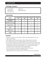
Package Content
• Power Supply
• User Manual
• AC Power Cord
• Cable Ties
• Mounting Screws
Connector
Caution
• Please do not store the power supply in a high humid temperature place, or to be
used in such condition.
• High voltages exist in the power supply. Unless authorized personnel, please
do not open the PSU cover. The warranty will be void if the cover is removed.
• Do not insert any objects into the open ventilation or fan grill area of the power supply.
• Please use ONLY genuine Rosewill modular cables. Third party cables might not be
compatible and could cause serious damage to your system and power supply.
The warranty will be voided with the use of third party cables.
• The 24 pin main power connector has a detachable 4 pin connector.
This 4 pin connector is not a P4 or ATX12V connector.
Please DO NOT force this cable in the P4 or ATX12V socket on the motherboard.
ATX 20+4 pin
EPS12V 8 pin
PCI-E 6+2 pin
SATA
Molex 4 pin
Floppy
Model
1
1
1
6
5
1
1
1
2
6
5
1
1
1
2
8
5
1
CAPSTONE
450
CAPSTONE
550
CAPSTONE
650
1
1
2
8
5
1
CAPSTONE
750
4
Installation
• Please make sure the power supply is not connected to the AC power cord.
• Make sure the I/O switch of the PSU is at off “O” position.
• Install the power supply into the chassis. (refer to your chassis manual)
• Please refer to your motherboard user manual to confirm 20-pin or 24-pin main
connector it needs. If 24-pin, you can plug the 24-pin main connector onto the
motherboard. If 20-pin, please detach the 4-pin to have a 20-pin main connector
then plug it onto the motherboard.
• Please refer to your motherboard user manual to confirm 4-pin ATX12V or
8-pin EPS12V connector it needs. If 8-pin, you can plug the 8-pin EPS12V connector
onto the motherboard. If 4-pin, please detach the 4-pin to have a 4-pin ATX12V
connector then plug it onto the motherboard.
• Connect the PCI-E connector to the VGA card if needed. Please refer to VGA card
manual to confirm 6-pin or 8-pin needed.
• Connect the SATA connector to the SATA HDD, Optical device if any.
• Connect the Molex connector to devices such as Optical device,
HDD, fan…etc.
• Connect the Floppy disk connector to the floppy drive if any.
• Please connect the other side of the cable to the PSU according to the instruction
on the PSU
• Make sure all the connectors are fully seated.
• Connect the AC power cord to the power supply.
• Turn on the power supply by pushing the I/O switch to the “I” position.
5
Easy Trouble shooting
If your PC system does not respond, please make following checks:
1. make sure the AC power cord is connected firmly and the AC power switch is
turned on.
2. Make sure all DC output connectors are connected in the right direction and
plugged firmly.
3. Check whether there is any short circuit problem or defective peripherals by
unplugging each peripheral device one at a time.
4. If one of the above mentioned problems occurs, please remove the fault and
wait for 1-2 minutes before you turn on the PSU again. This is necessary to
release the latch condition of the protection circuit.
5. If the PSU is still unable to power up after above checks, please contact with
your dealer for service.
Information
Thank you for purchasing a High-Quality Rosewill Product.
Please register your product at :
www.rosewill.com
for complete warranty
information and future support for your product.If you have any question while
using our products, please feel free to contact us at
Support Phone Number: 800-575-9885
Support Email: [email protected]
128mm
188mm


