Rosen DS-UN1010-H11 Installation Manual Download Page 4


Installation Guide VW Series


Rosen Entertainment Systems 


Copyright 2010 All Rights Reserved 

 Installation Guide 


DP-VW0714HD  Rev E 


Page 4 

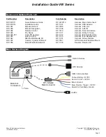
LOCATING REMOTE COMPONENTS 


You will need to mount the GPS and Optional Satellite Radio Antennas on the exterior of the 

vehicle.   And mount the iPod Interface Connector in the vehicle. The following steps will help guide 

you through this process. 


STEP

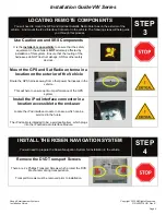
Use Caution around SRS Components 


I

t is the 

installer’s responsibility

 to ensure that the safety 

equipment in the vehicle is 

NOT

 adversely affected by 

installation of this system.  Ensure that the routing of the 

harnesses do NOT obstruct airbags, SRS or other safety 

devices.


Mount the GPS and Sat Radio antenna in a 

location on the exterior of the Vehicle 


Route the GPS harness away from other power harnesses in the 

vehicle.  


This will help to ensure optimum performance of the GPS 

system.


Install the iPod interface connector in a 

location accessible to the end-user 


Locate the iPod interface module in an area which can be 

serviced in the future.   


The iPod cable is intended to be a serviceable item, which plugs 

into the iPod/Sat radio Interface Module.


INSTALL THE ROSEN NAVIGATION SYSTEM 


You will need to prepare the Rosen Navigation System for installation in the vehicle.


STEP

4


Remove the DVD Transport Screws


There are 2 x Phillips Transport Screws which protect the DVD 

Mechanism during transportation.   


Transport Screws must be removed prior to installation. 


Summary of Contents for DS-UN1010-H11

Page 1: ...COULD RESULT IN SERIOUS INJURY OR DEATH AND COULD ALSO VIOLATE STATE AND OR FEDERAL LAW ROSEN ENTERTAINMENT SYSTEMS DISCLAIMS ANY LIABILITY FOR ANY BODILY INJURY OR PROPERTY DAMAGE THAT MAY RESULT FROM ANY IMPROPER OR UNINTENDED INSTALLATION AND OR USE STOP Damage to the vehicle may occur Do not proceed until process has been completed CAUTION CAUTION Process must be carefully observed in order to...

Page 2: ...ections and Technical Tips about this product and installation www RosenDealerCentral com CHECK THE BATTERY Test the battery voltage to make sure it s fully charged This only takes seconds and can save hours of troubleshooting later TURN THE VEHICLE OFF Keep the Vehicle Off during the installation to avoid setting various Vehicle Faults Keep the Vehicle OFF during the installation Failure to follo...

Page 3: ...n pry tool to carefully lift the Upper grill Use Caution the plastic is fragile and excess force can break or damage trim CAUTION Remove the Inner Trim Vent Components Remove 3 x T 20 Torx screws to release the inner Trim Vent components Remove the Radio Surround Trim Remove 2 x T 20 Torx screws to release Radio Surround Trim Remove the Radio Mounting Screws Remove 4 x T 20 Torx screws to release ...

Page 4: ... airbags SRS or other safety devices Mount the GPS and Sat Radio antenna in a location on the exterior of the Vehicle Route the GPS harness away from other power harnesses in the vehicle This will help to ensure optimum performance of the GPS system Install the iPod interface connector in a location accessible to the end user Locate the iPod interface module in an area which can be serviced in the...

Page 5: ...nesses for connection to the Rosen Harness Use care not to pinch or damage cables as this will cause performance issues failures CAUTION Engage all Connectors to the Factory Harnesses and attach the Rosen System using the previously removed Mounting Screws Attach the system with 4 x T 20 Torx Screws Turn the vehicle ON and confirm the unit is fully operational With the connectors Fully Engaged tur...

Page 6: ...ll the Inner Trim Vent Components Install 3 x T 20 Torx screws to attach the inner Trim Vent components Install the Upper Trim Vent Component Use caution when installing the Upper Trim Vent Component as it can easily be deformed or damaged CAUTION ENABLE INSTALLER SETTINGS You will need to select certain Installer Setting based on any Optional Equipment that you may have installed STEP 6 Launch th...

Page 7: ...nnectors are properly installed 3 Check the Vehicle and System Fuses Select RADIO as the Source Confirm that the AM and FM reception are as expected Troubleshooting 1 Confirm both Antennas are properly connected 2 Confirm the Factory Sat Antenna green has not been used 3 Reset the System Select SATELLITE RADIO as the Source Confirm Channel 001 is present after 5 minutes Troubleshooting 1 Confirm t...

Page 8: ... exists in the Favorites Folder 2 Reset the system Select Phone as the Source Confirm Phone Pairing is successful Troubleshooting 1 Confirm the Phone has BT and is in discoverable mode 2 Confirm the Phone is compatible with the system 3 Reset the system Select NAV as the Source Confirm the Navigation loads and signal strength is OK Troubleshooting 1 Confirm the antenna has an unobstructed view of ...

Page 9: ...04 Remote Control DP 1010 Harness Sensors Camera DP 1023 Pin Stylus DP 1011 Harness Dolby 5 1 Amp DP 1020 H11 Card SD w maps DP 1013 Harness iPod Interface Box DP 1022 Antenna GPS DP 1015 Harness iPod Replacement DP 1042 XM iPod Multimedia Kit DP 1051 Harness Sirius Interface DP 1035 Camera Cylinder W Mount DP 1047 GPS Antenna Windshield Mount DP 1055 Sirius iPod Multimedia Kit DP 1030 Sensors Rev...

Page 10: ...Installation Guide VW Series Rosen Entertainment Systems Copyright 2010 All Rights Reserved Installation Guide DP VW0714HD Rev E Page 10 Option Harness Diagram ...

Page 11: ...Installation Guide VW Series Rosen Entertainment Systems Copyright 2010 All Rights Reserved Installation Guide DP VW0714HD Rev E Page 11 ...

Reviews: