Rosen Aviation
MIP
Document Number: 109970
Page 4 of 12
Revision A
Date: 04/24/18
1. INTRODUCTION
This manual provides general instructions about how to install the MIP (Media Input Panel). It
contains everything you need to know to wire the components and confirm that the system is
functioning correctly.
Note:
Only trained and qualified personnel should perform installation and service.
1.1. System Overview
The MIP takes in Audio Video signals and converts them into (2) redundant 3G SDI outputs.
SDI outputs are encrypted and require Rosen monitors to decrypt. The MIP also has an
analog stereo output. It also has a USB port for charging or sending data to an RVA
(RosenView Access) monitor.
The
MIP
Outline and Installation
Drawings
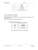
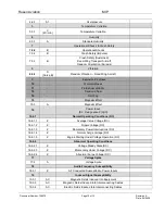
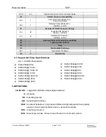
(P/N MIP100-002 & MIP100-003) provide detailed
information about the MIP. Refer to these drawings for mechanical and electrical interface
information and performance specifications. Key items found on this drawing include:
Overall dimensions
Weight
Mounting features
Electrical connectors and pin-outs
Power, environmental, and image performance specifications
2. INSTALLATION GUIDELINES
2.1. Suggested installation
For part details see Outline and Installation drawing (P/N MIP100-002-CD & MIP100-003-
CD).
2.2. Cooling and Ventilation
The MIP does not require any external forced-air cooling. For venting requirements see
Outline and Installation drawings (P/N MIP100-002-CD & MIP100-003-CD).
2.3. Electrical Requirements
Operational Voltage Range: 18 to 32 VDC
For Max Current see
Outline and Installation
drawing.


