background image

MODELS 


RackView LCD Panel Manual 

3


RackView LCD Panel Models 

The RackView LCD panel is available in 10 different models. The main difference between each of the models 

is the display size and video resolution capabilities. There are several options available that can differ with 

each model of RackView LCD panel. The options for each model are explained in the Appendix pages of this 

manual. The two illustrations below show the general layout of the front and back panels as applicable to all 

RackView LCD Panel models. 


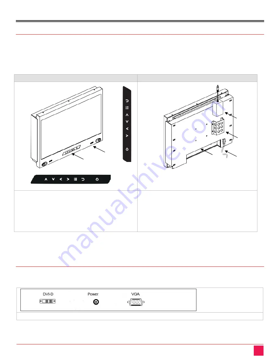
RackView LCD Panel – front view 

RackView LCD panel – rear view 


1.  LCD display 
2.  LCD membrane 
3.  Audio speaker 
4.  LCD membrane – vertical 
5.  LCD membrane - horizontal 

6.  Location for connectors 
7.  Power cord 
8.  Power supply bracket 
9.  External power supply 

Figure 1. RackView LCD Panels – front and rear layout 

Depending on the RackView LCD Panel display, the push-button membrane panel can be either horizontally 

mounted underneath the display, or vertically mounted to one side of the display. 


RackView LCD Panel - Rear Connector Layout 

The RackView LCD rear panel includes an HD15(KVM) and DVI-D connector as standard. This diagram shows 

the approximate positioning of the connectors on the rear panel. 


RackView LCD Panel - rear panel connector layout for the standard interface 

Figure 2. RackView LCD panel - rear panel connector layout 


Summary of Contents for RackView RVR-LCDA17-4K

Page 1: ...RackView LCD Panel Rack Mount LCD Display Panel Installation and Operation Manual 10707 Stancliff Road Houston Texas 77099 Phone 281 933 7673 techsupport rose com...

Page 2: ...age in transit to prepay shipping charges to the warranty service location and to use the original shipping container or its equivalent You must call for a return authorization number first Under no c...

Page 3: ...al environment This equipment generates uses and can radiate radio frequency energy and if not installed and used in accordance with the instruction manual may cause harmful interference to radio comm...

Page 4: ...LCD panels 8 Figure 5 OSD operation and control 9 Figure 6 OSD configuration and settings 10 Figure 7 PIP and PBP settings and operation 11 Figure 8 PIP and PBP video sources 12 Figure 9 Schematic sho...

Page 5: ...t Numbers 16 Appendix C Weight and Dimensions 17 Appendix D Touchscreen Options 18 Appendix E RackView LCD Panel Video Options 19 Appendix F Multi LCD Panel Display Control 22 Appendix G RackView DC P...

Page 6: ...e instructions in this manual assume a general knowledge of computer installation procedures familiarity with cabling requirements and some understanding video display device operation Features Rackmo...

Page 7: ...accessories Additional Items Required M6 mounting screws and cage nuts are normally provided as accessories with the rack cabinet and not with the RackView LCD panel Before Installation It is very im...

Page 8: ...view 1 LCD display 2 LCD membrane 3 Audio speaker 4 LCD membrane vertical 5 LCD membrane horizontal 6 Location for connectors 7 Power cord 8 Power supply bracket 9 External power supply Figure 1 RackV...

Page 9: ...kView LCD Panel Chassis Dimensions The front side and bottom dimensions of each of the RackView LCD panels are shown in millimeters RackView LCD Panel 17 RackView LCD Panel 19 RackView LCD Panel 20 Ra...

Page 10: ...RackView LCD Panel Manual 5...

Page 11: ...6 RackView LCD Panel 17 FHD RackView LCD Panel 19 Widescreen RackView LCD Panel 21 FHD Figure 3 Chassis dimensions and LCD panel graphics Please check Appendix C for a listing of all RackView LCD Pan...

Page 12: ...splay panel with an M6 screw set M6 screw x 4 pcs required Left right side M6 screw sets are not provided Step 2 Fix the LCD into the rack Installation Steps for RackView LCD Panel 20 Step 1 Mount the...

Page 13: ...2 Insert the upper part of the RackView display panel into the rear bracket Step 3 Push the lower part of the RackView display panel into the rear bracket Step 4 Fix the RackView display panel into th...

Page 14: ...n Display is activated by pressing the buttons on the front panel of the display frame The push button membrane control panel may be mounted horizontally or vertically on the display panel however the...

Page 15: ...and distortion Clock Adjust the clock value Phase Adjust the phase value H Position Align the screen image left or right V Position Align the screen image up or down Audio Audio mode Movie Voice Norm...

Page 16: ...gs PIP Mode Display the Sub screen in the Main screen OSD Menu MISC PIP Mode Large Small OFF PIP Position Adjust the position of the Sub screen top left bottom left top right bottom right OSD Menu MIS...

Page 17: ...t the size of the Sub screen Large Small OSD Menu MISC PBP Mode Large Small PIP PBP Source To select an input signal for PIP PBP Sub screen OSD Menu MISC PIP Source VGA S Video Composite DVI HDMI SDI...

Page 18: ...power cords power adapter and connection cables designed for this Unit Keep objects that might damage this Unit and liquids that may spill clear from this Unit Liquids and foreign objects might come i...

Page 19: ...ntainer or equivalent insured and shipped to Rose Electronics Attn RA __________ 10707 Stancliff Road Houston Texas 77099 USA Technical Support If you are experiencing problems or need assistance inst...

Page 20: ...Audio option 2 3 5mm with L R Speakers Impedance 30K 750mV HDMI DisplayPort Model Speaker Power 2 2W Temperature Relative Humidity Operating Temperature 32 F to 131 F 0 C to 55 C Storage Temperature 4...

Page 21: ...1200 RVR LCDA21 DVI Kn 21 LCD Panel Widescreen 1920 1080 RVR LCDA24 DVI Kn 24 LCD Panel Widescreen 1920 1200 RVR LCDA23 4K Kn 23 LCD Panel 4K Widescreen 3840x2160 RackView LCD Panel Options TSR Resist...

Page 22: ...h 529 x 124 x 451 mm 9 2lb 4 2kg 13 6lb 6 2 kg 19 LCD 18 9 x 2 1 x 14 inch 480 x 53 x 355 mm 21 2 x 5 1 x 20 8 inch 539 x 129 x 529 mm 12 5lb 5 7kg 17 6lb 8 0kg 19 LCD Widescreen 18 9 x 2 3 x 12 2 inc...

Page 23: ...Finger Finger Activation Force 50g Stylus R0 8 50g Durability 10 35 million touches 300 million touches Response Time 15ms 20ms Optical Transmittance 80 3 87 93 2 Surface Hardness 3H 9H Haze 8 3 7 Con...

Page 24: ...K and HDMI video interface as standard All other RackView Panels have DVI and VGA as the standard video interface RackView Model DVI S Video BNC DVI HDMI S Video DVI HDMI S Video SDI 17 LCD Yes Yes Ye...

Page 25: ...akers installed 3 All Video Audio options must be factory fitted at the time of order Video Formats 3G HD SD SDI Description Video Signal Resolution Refresh Rate Signal Input 3G SDI In BNC x 1 0 8Vp p...

Page 26: ...o all models 1280 x 1024 x 60Hz 75Hz Applies to all models Applies to all models 1280 x 960 x 60Hz Applies to all models Applies to all models 1280 x 768 x 60Hz 75Hz Applies to all models Applies to a...

Page 27: ...unted inside each RackView LCD panel This control card is configured with DVI D VGA HDMI S Video BNC and audio connectors It also has 2 dip switches 2 RJ45 CATx ports In Out and a DB9 RS 232 serial po...

Page 28: ...cified in the table below Select the DC voltage required then add the voltage to the RackView part number as nnnDC For example adding 48VDC to a RackView 17 would result in RVR LCDA17 DVI Kn 48DC part...

Page 29: ...s are available for integration with the RackView LCD Panel For further information on these connectors please contact Rose Electronics Input Product MIL Standard MIL Type Connector DC Power Male MIL...

Page 30: ...COM sales rose com 800 333 9343 Rose Electronics 10707 Stancliff Road Houston Texas 77099 Rose USA 281 933 7673 Rose Europe 49 0 2454 969442 Rose Asia 65 6324 2322 Rose Australia 61 0 421 247083 WWW...

Reviews: