Mounting and Installation
Version 2
RES-5008
Page 15
7.3
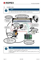
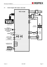
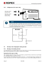
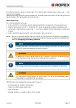
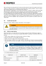
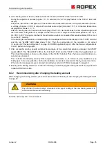
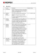
Mains connection
Line
To avoid disturbances while measuring, place several con-
trol loops on the same phase if possible.
Overcurrent device
2-Pole circuit breaker or fuses,
(
ROPEX application report).
ATTENTION
- protection only in the event of
a short circuit.
No
protection
of
the
RESISTRON
®
Temperature Controller.
Contactor Ka
For all-pole disconnection, EMERGENCY OFF or EMER-
GENCY STOP.
Dimensioning
ROPEX application report
Line filter
Filter type and filter size must be based on load, trans-
former and machine cabling (
ROPEX application
report).
CAUTION
Do not lay filter supply lines (mains
side) parallel to filter output lines (load side).
RESISTRON
®
Temperature Controller
Contactor Kb
CAUTION To increase machine safety by
switching off the load on all poles in the event
of a fault, e.g. in combination with the ALARM
output of the RESISTRON
®
Temperature Controller.
Dimensioning
ROPEX application report I
1max
(for Ka and Kb)
Impulsetransformer
Design according to EN 61558 or UL 5058 (isolating trans-
former with reinforced insulation). Ground core.
CAUTION
Use only single-chamber design.
Power, ED number and voltage values must be
determined
individually
depending
on
the application (
ROPEX application report)
.
Wiring
Cable cross-sections depend on the application
(
ROPEX application report).
Make sure to twist (min. 20 beats/meter,
Accessories
“
twisted measuring line
”
)
Twisting (min. 20 beats/meter) necessary if
several control loops are laid together
(
“
Crosstalk
”
).
Twisting (min. 20 beats/meter) recommended to
improve EMC properties.
ROPEX
temperature
controller
UR
IR
R
PRIM.
U1
Kb
Ka
SEC.
U2
LINE
I
>
I
>
GND/
Earth
N (L2)
L1 (L1)
LINE
FILTER
ON
OFF
Kc
3
3
3
1
Short wires
2
2

