


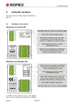


Controller functions
RES-403
Page 23
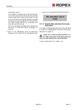
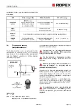
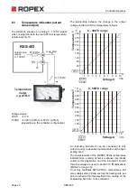
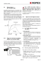
The set point that is selected for the heatsealing tempe-
rature must be greater than 40°C. If not, the heatse-
aling band will not be heated up ("HEAT" LED blinks).
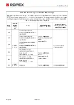
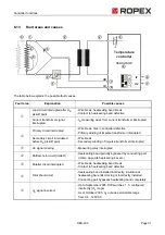
The alarm output is switched if the "START" signal is
activated while an error message is indicating error
codes 104…106, 111…114, 211, 302 or 303 (up to
September 2005: error codes 8…12) (
ª
section 6.12
"Error messages" on page 26). The heatsealing band is
no longer heated up.
6.6
Measuring impulse duration
(as of October 2005)
The length of the measuring impulses generated by the
controller can be set with the parameter. It may be
necessary to set a measuring impulse that is longer
than the default 1.7ms for certain applications
(
ª
ROPEX Application Report).
This parameter can only be set by means of the
ROPEX visualization software (
ª
section 6.10 "Dia-
gnostic interface/visualization software (as of October
2005)" on page 25).
6.7
Automatic phase angle
compensation (AUTOCOMP)
(as of October 2005)
It may be necessary to compensate the phase angle
displacement between the U
R
and I
R
measuring
signals in certain heatsealing applications (
ª
ROPEX
Application Report). The "AUTOCOMP" function is
provided for this purpose.
The "AUTOCOMP" function must be activated in the
ROPEX visualization software (
ª
section 6.10 "Dia-
gnostic interface/visualization software (as of October
2005)" on page 25).
The following settings are possible:
1.
„OFF" (Factory settings)
The „AUTOCOMP“ function is deactivated.
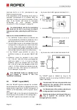
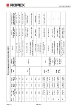
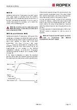
2.
„ON“
The „AUTOCOMP“ function is executed whenever
the "AUTOCAL" function (
ª
section 6.4 "Automatic
zero calibration (AUTOCAL)" on page 21) is run
twice in quick succession. The interval between the
end of the first "AUTOCAL" function and the start of
the second "AUTOCAL" must be shorter than 2.0s.
The second "AUTOCAL" function only takes around
2.0s and incorporates the "AUTOCOMP" function.
If the interval following a successful "AUTOCAL"
function is longer than 2.0s, the display returns to
the home position without executing the „AUTO-
COMP“ function.
The "OUTPUT" LED blinks repeatedly when the
"AUTOCOMP" function is executed and the actual
value output (terminals 17+14) is set to 0…3°C
(i.e.approx. 0VDC).
3.
„AUTO“
(as of software revision 108)
With this setting the „AUTOCOMP“ function is acti-
vated automatically after the "AUTOCAL" function
has been successfully executed.
Function
AUTOCAL
signal
"AC"
t
t
0
0
AUTOCAL
lit
t
OFF
<2.0s
AUTOCOMP
"AUTOCAL"
t
OFF
LED
lit
"OUTPUT"
LED
"AP"
24VDC


