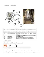
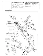
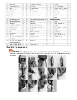
Rongpeng R470 220V Operating Instruction And Safety Manual Download Page 17


17 


Parts list 

No. 

Description 

Qty. 

No. 

Description 

Qty. 

No. 

Description 

Qty. 

Filter assembly 

50 

Powder metallurgy gear shaft collar 

100 

O-Rings(27x2.4) 

Ribbon 

51 

Gear shaft 

101 

Cap 

Feed pipe bending 

52 

Pinion   

102 

Allen  flat  end  set  screws 

M3X10 

cutting ferrule 

53 

Bent axle 

103 

Deflating cap 

Feeding hose 

54 

Crankshaft gear 

104 

Micro switch cover 

Pressure release tube 

55 

Retaining 

ring 

in 

the 

powder 

metallurgy 

105 

Adjust seat 

Pressure  release tube  locking 

ring components 

56 

Gear shaft collar 

106 

Micro 

switch 

comCasing 

Hose hoops 

57 

Crank shaft collar 

107 

Pressure spring 

Feed pipe bending contact 

58 

Open punching needle roller bearing 

108 

Spring hat 

10 

O-Rings 19*2.65 

59 

Straight pin 

109 

Pressure adjusting screw 

11 

Feed pipe bending    clasp 

60 

Motor cabinet 

110 

Regulating sleeve 

12 

Pump body fixed nut 

61 

Wave spring washers 

111 

Filter holder 

13 

The plunger rod lock nut 

62 

Single-row radial ball bearing 

112 

Filter net 

14 

The plunger rod lock nut liner 

63-64 

Motor assembly 

113 

Filter element 

15 

The little ring 

65 

Single row radial ball bearing 

114 

O-Rings 24.3X1.8 

16 

Discharge joint 

66 

Motor stator components 

115 

A filter element knob 

17 

Pump body 

67 

Motor parameter data 

116 

Plastic spacer 

18 

Large Sealing Packing Ring 

68 

Carbon brusf seat 

117 

Screw seat insert 

19 

The plunger rod guide sleeve 

69 

Carbon brush cover 

118 

Pressure relief valve seat 

20 

Rectangular Seal Ring 

70 

The motor back cover seat 

119 

Plastic ring 

21 

  Steel ball seat 

71 

Homemade bolt 

120 

O-Rings 5X1.8 

22 

Feed valve ball 

72 

plain washer 6 

121 

Pressure  relief  valve  stem+4.5 

Carbide Ball 

23 

Feed valve plates 

73 

locking nut M6 

122 

Pressure relief valve spring 

24 

Feeding seat sealing 

74 

Blade 

123 

Spring seat 

25 

Feeding seat 

75 

Split damping ring 

124 

Elastic cylindrical pin 3X8 

26 

The plunger rod valve lock nut 

76 

The motor back cover 

125 

Switch seat 

27 

Squirrel cage gasket 

77 

Cross  pan  head  self-drilling  screw 

ST3.5X10 

126 

Switches knob 

28 

Plunger rod valve plates 

78 

Control circuit device 

127 

Straight pin A2.5X25 

29 

Steel ball 

79 

Cross  pan  head  self-drilling  screw 

ST4.8X20 

128 

Pressure aluminium joint 

30 

Mouse cage 

80 

shell(Silver sand grain63358) 

129 

Plastic cup 

Summary of Contents for R470 220V

Page 1: ...oatings Contents 1 Must be grounded Read Grounding instructions Use only grounded electrical outlets or Ground equipment and conductive objects in work area 2 Have heart problem or with heart pacemake...

Page 2: ...4 Paint or solvent flowing through the equipment is able to result in static electricity Static electricity creates a risk of fire or explosion in the presence of paint or solvent fumes All parts of t...

Page 3: ...painting 2 Do not operate or spray near children Keep children away from equipment at all times 3 Don not overreach or stand on an unstable support Keep effective footing and balance at all times 4 St...

Page 4: ...when flammable fumes are present Ground equipment and conductive objects in work area Read Grounding instructions If there is static sparking or you feel a shock stop operation immediately Do not use...

Page 5: ...oses to pull equipment Comply with all applicable safety regulations Keep children and animals away from work area Do not operate the equipment when fatigued or under the influence of drugs or alcohol...

Page 6: ...d reminding the user to be aware of the recommendations of the coating material manufacturer D Surface temperatures of any part of the machine reachable during normal operation maintenance and servici...

Page 7: ...be plugged into an outlet that is properly installed and Number Description Function Introduction 01 Pressure Adjust Knob Control output pressure of Paint Clockwise increase pressure anticlockwise de...

Page 8: ...ith an appropriate grounding contact Never use an outlet that is not grounded or an adapter Do not use the sprayer if the electrical cord has a damaged ground contact Only use an extension cord with a...

Page 9: ...the Spray Gun Always lock the trigger off when attaching the spray tip or when thr spray gun is not in use Locking the Spray Gun Unlocking the Spray Gun The gun is secured when To unlock the gun turn...

Page 10: ...een the braid layers FEATURES Polyurethane cover permits greater flexibility and tighter bends Resistant to flex fatigue Dissipates static charge Will not swell or degrade in contact with most paint c...

Page 11: ...the pump is clean and sufficient in volume then begin the following procedure 1 Remove spray tip from gun 2 Put the input hose and pressure relief tube into the bucket with some water 3 Turn on the mo...

Page 12: ...l has been removed from under the cap on the hydraulic tank Hydraulic tank should be at least 3 4 full of hydraulic fluid 1 During paint spraying hold the gun upright to the surface of paint object an...

Page 13: ...raying Check or service equipment or install or clean spray tip 1 Engage trigger safety lock on gun Turn Off power and turn sprayer pressure control to lowest pressure setting 2 Hold gun against side...

Page 14: ...enever you service sprayer Do not operate the sprayer without the motor shroud in place Replace if damaged Motor shroud directs cooling air around motor to prevent overheating and insulates the contro...

Page 15: ...warm area to thaw Do not start sprayer until thawed completely If paint hardened dried in sprayer replace pump packings 2 Displacement pump connecting rod pin Pin must be completely pushed into connec...

Page 16: ...rbon dust by using compressed air to blow out brush dust 10 Low stall pressure Turn pressure control knob fully clockwise 10 Replace pressure control assembly 11 Motor armature for shorts by using an...

Page 17: ...ly 1 113 Filter element 1 15 The little ring 1 65 Single row radial ball bearing 1 114 O Rings 24 3X1 8 1 16 Discharge joint 2 66 Motor stator components 1 115 A filter element knob 1 17 Pump body 1 6...

Page 18: ...spray gun 1 41 Cross Recess Head Screw 10 91 Hexagon socket cap screws 1 139 description 1 42 Pump body cover 1 92 Transporting pipe components 1 140 High voltage paint 7 6m black 1 43 Dust Stop block...

Page 19: ...take out the ring size 6 In the size of ring outer ring with a little grease Press the ring into the pump body 7 Press the plunger rod into the pump body 8 Put Into the pump body components according...

Page 20: ...20 1 Left Secondary Frame With Handle Grip 1PCS 2 Right Secondary Frame With Handle Grip 1PCS 3 White Seal Washer 3PCS 4 Black Seal Washer 2PCS...

Reviews: