background image

3

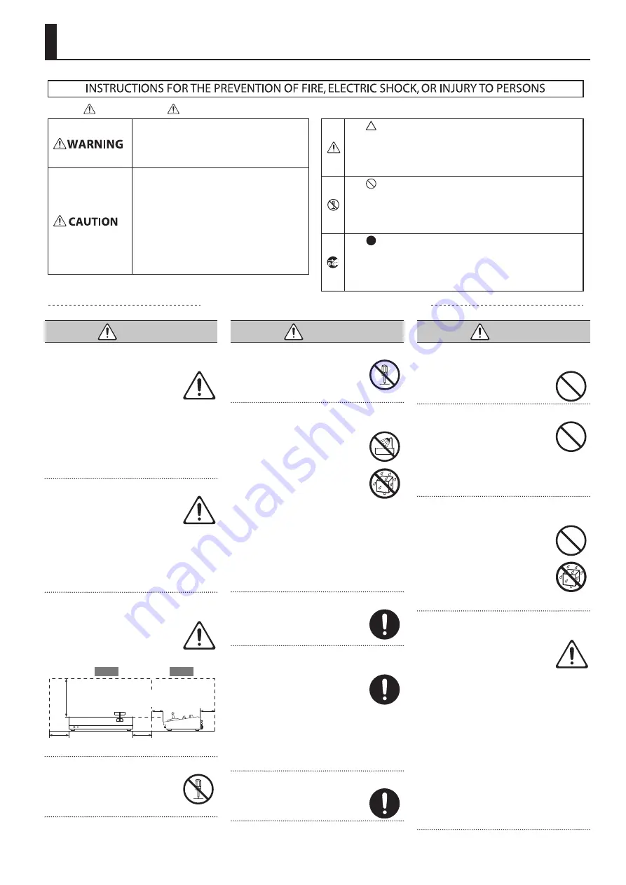
USING THE UNIT SAFELY

 WARNING

To completely turn off power to the unit, pull out 

the plug from the outlet

Even with the power switch turned 

off, this unit is not completely 

separated from its main source of 

power. When the power needs to 

be completely turned off, turn off the power 

switch on the unit, then pull out the plug 

from the outlet. For this reason, the outlet 

into which you choose to connect the power 

cord’s plug should be one that is within easy 

reach and readily accessible.

Concerning the Auto Off function

The power to this unit will be 

turned off automatically after a 

predetermined amount of time 

has passed since it was last used 

for playing music, or its buttons or controls 

were operated (Auto Off function). If you 

do not want the power to be turned off 

automatically, disengage the Auto Off 

function (p. 11).

Secure a sufficient amount of space at the setup 

location

Since this unit normally emits a 

slight amount of heat, make sure to 

secure sufficient space around it, as 

shown below.

30 cm (12 in.) 

or greater

20 cm (8 in.) 

or greater

20 cm (8 in.) 

or greater

15 cm (6 in.) 

or greater

5 cm (2 in.) 

or greater

Side

Front

Do not disassemble or modify by yourself

Do not carry out anything unless 

you are instructed to do so in the 

owner’s manual. Otherwise, you 

risk causing malfunction.

 WARNING

Do not repair or replace parts by yourself

Refer all servicing to your retailer, 

the nearest Roland Service Center, 

or an authorized Roland distributor, 

as listed on the “Information.”

Do not use or store in the following types of 

locations

•  Subject to temperature extremes 

(e.g., direct sunlight in an 

enclosed vehicle, near a heating 

duct, on top of heat-generating 

equipment); or are

•  Damp (e.g., baths, washrooms, 

on wet floors); or are

•  Exposed to steam or smoke; or are
•  Subject to salt exposure; or are
•  Exposed to rain; or are
•  Dusty or sandy; or are
•  Subject to high levels of vibration and 

shakiness; or are

•  Placed in a poorly ventilated location.

Do not place in an unstable location

Otherwise, you risk injury as the 

result of the unit toppling over or 

dropping down.

Use only the supplied AC adaptor and the correct 

voltage

Be sure to use only the AC adaptor 

supplied with the unit. Also, 

make sure the line voltage at the 

installation matches the input 

voltage specified on the AC adaptor’s body. 

Other AC adaptors may use a different 

polarity, or be designed for a different 

voltage, so their use could result in damage, 

malfunction, or electric shock.

Use only the supplied power cord

Use only the attached power cord. 

Also, the supplied power cord must 

not be used with any other device.

 WARNING

Do not bend the power cord or place heavy objects 

on it

Otherwise, fire or electric shock 

may result.

Avoid extended use at high volume

Use of the unit at high volume 

for extended periods of time may 

cause hearing loss. If you ever 

experience any hearing loss or 

ringing in the ears, you should immediately 

stop using the unit and consult a specialized 

physician.

Do not allow foreign objects or liquids to enter 

unit; never place containers with liquid on unit

Do not place containers containing 

liquid (e.g., flower vases) on this 

product. Never allow foreign 

objects (e.g., flammable objects, 

coins, wires) or liquids (e.g., water 

or juice) to enter this product. 

Doing so may cause short circuits, 

faulty operation, or other malfunctions.

Turn off the unit if an abnormality or malfunction 

occurs

Immediately turn the unit off, 

remove the AC adaptor from the 

outlet, and request servicing by 

your retailer, the nearest Roland 

Service Center, or an authorized Roland 

distributor, as listed on the “Information” 

when:

•  The AC adaptor or the power cord has 

been damaged; or

•  If smoke or unusual odor occurs; or
•  Objects have fallen into, or liquid has been 

spilled onto the unit; or

•  The unit has been exposed to rain (or 

otherwise has become wet); or

•  The unit does not appear to operate 

normally or exhibits a marked change in 

performance.

Used for instructions intended to alert the 

user to the risk of injury or material 

damage should the unit be used 

improperly. 
* Material damage refers to damage or 

other adverse effects caused with 

respect to the home and all its 

furnishings, as well to domestic animals 

or pets. 

Used for instructions intended to alert the 

user to the risk of death or severe injury 

should the unit be used improperly. 

The       symbol alerts the user to things that must be 

carried out. The specific thing that must be done is 

indicated by the design contained within the circle. In the 

case of the symbol at left, it means that the power-cord 

plug must be unplugged from the outlet. 

The       symbol alerts the user to important instructions or 

warnings.The specific meaning of the symbol is 

determined by the design contained within the triangle. In 

the case of the symbol at left, it is used for general 

cautions, warnings, or alerts to danger. 
The       symbol alerts the user to items that must never be 

carried out (are forbidden). The specific thing that must 

not be done is indicated by the design contained within 

the circle. In the case of the symbol at left, it means that 

the unit must never be disassembled. 

About       WARNING and       CAUTION Notices

About the Symbols

ALWAYS OBSERVE THE FOLLOWING

Summary of Contents for V-60HD

Page 1: ...EM 0 VERSION Owner s Manual this document Read this first It explains the basic things you need to know in order to use the V 60HD PDF Manual download from theWeb 5 5 Reference Manual This manual covers all menu items of the V 60HD It also describes control via RS 232 LAN and TALLY GPI To obtain the PDF manual 1 Enter the following URL in your computer https proav roland com I 2 Go to the V 60HD p...

Page 2: ...e Sound Position Pan 24 Adjusting the Volume Balance 25 Outputting AUX bus Audio 25 Applying Effects to Audio 26 Applying Effects to Input Audio 26 Applying Effects to Output Audio 27 Controlling Volume Levels Automatically Auto Mixing 28 Muting Out Specific Input Audio Mute 28 Interlinking Audio Output to Video Switching Audio Follow 29 Separating Discrete Analog Input Audio Streams and Adding Th...

Page 3: ...only the attached power cord Also the supplied power cord must not be used with any other device WARNING Do not bend the power cord or place heavy objects on it Otherwise fire or electric shock may result Avoid extended use at high volume Use of the unit at high volume for extended periods of time may cause hearing loss If you ever experience any hearing loss or ringing in the ears you should imme...

Page 4: ...and cause the unit to fall or topple Avoid climbing on top of the unit or placing heavy objects on it Otherwise you risk injury as the result of the unit toppling over or dropping down Never connect disconnect a power plug if your hands are wet Otherwise you could receive an electric shock Disconnect all cords cables before moving the unit Before moving the unit disconnect the power plug from the ...

Page 5: ...correct operation etc To protect yourself against the irretrievable loss of data try to make a habit of creating regular backups of the data you ve stored in the unit Roland assumes no liability concerning the restoration of any stored content that has been lost Use a reasonable amount of care when using the unit s buttons sliders or other controls and when using its jacks and connectors Rough han...

Page 6: ...MASTER OUTPUT level meter This displays the volume level for master out 4 PinP 1 button PinP 2 button SPLIT button This switches PinP or split video composition on and off When the feature is turned on the button lights up p 21 p 22 H PGM CTR knob PinP This adjusts the horizontal display position of the inset screen Split This adjusts the vertical and horizontal position of the video displayed abo...

Page 7: ...tches between displaying or hiding the menu The menu appears on the unit s built in display and on the multi view monitor p 10 connected to the MULTI VIEW connector p 11 EXIT knob This returns you to the menu one level higher VALUE knob Turning This selects a menu item or changes a setting value Pressing This accepts the selected menu item or applies changes to a setting It also executes operation...

Page 8: ...the OSD menu p 10 You connect a multi view monitor here POWER button This turns the power on and off p 11 HDMI IN 5 and 6 connectors RGB COMPONENT IN 6 connector SDI OUT 1 and 2 connectors HDMI OUT 1 and 2 connectors This outputs the results of video mixing the final output video preview video the video to be output next or AUX bus video Connect them to devices such as projectors video recorders o...

Page 9: ...phones that require phantom power You risk causing damage if you mistakenly supply phantom power to dynamic microphones audio playback devices or other devices that don t require such power Be sure to check the specifications of any microphone you intend to use by referring to the manual that came with it This instrument s phantom power 48 V DC 14 mA Max Front Panel Grounding terminal Connect this...

Page 10: ...This displays video input via channels 1 6 and still images assigned to channels 7 and 8 The final video output and preset video the video to be output next are displayed with tally borders Channel information 1 2 3 1 When the Audio Follow feature is on p 29 the A F symbol is displayed 2 When video or a still image is being sent to the AUX bus p 18 the AUX symbol is displayed 3 This displays a lev...

Page 11: ...ton0 SYSTEM 0set AUTO OFF to OFF NOTE 5 5 Any settings that you are in the process of editing will be lost when the power is turned off If you have any settings that you want to keep you should save them beforehand 5 5 To restore power turn the power on again Operating the Menu This makes menus appear on the built in display for making settings for video and audio or for the V 60HD itself The OSD ...

Page 12: ...waver This is due to progressive conversion and is not a malfunction About frame rates Frame rates that can be input are 59 94 Hz and 50 Hz Inputting video at a frame rate other than these might result in no output or dropped frames To change the frame rate press the MENU button0 SYSTEM 0 FRAME RATE SettingtheInputFormatsforChannels5and6 By factory default the EDID assignment for channels 5 and 6 ...

Page 13: ...he test pattern 1 Select the MENU button0 VIDEO OUTPUT 0the output video A menu for the selected output video appears 2 Select a menu item then use the VALUE knob to adjust the output video SDI OUT 1 and 2 SDI OUT 1 and 2 connectors Menu item Explanation 3G SDI MAPPING This sets the mapping structure for 3G SDI output H FLIP Setting this to ON flips the output video horizontally BRIGHTNESS This ad...

Page 14: ...nnector p 12 1 This is available when SCALING TYPE is set to MANUAL HDMI RGB IN 6 HDMI IN 6 connector 2 RGB COMPONENT IN 6 connector 2 Menu item Explanation AUTO SAMPLING 3 This automatically adjusts the image quality Depending on the video adjusting the image quality might not be possible FLICKER FILTER Setting this to ON reduces flicker ZOOM This adjusts the zoom ratio SCALING TYPE This sets the...

Page 15: ... Video To input copyright protected HDCP video from a Blu ray Disc player or the like follow the steps described below to change the HDCP setting The V 60HD must be connected to an HDCP compatible display for HDCP protected video to be connected What s HDCP HDCP is copyright protection technology that prevents unlawful copying of content by encoding the path when sending digital signals from a vid...

Page 16: ...knob to select PGM PST or A B and set the operation mode 3 Press the VALUE knob to apply the setting 4 Press the MENU button to quit the menu Switching Using the PGM PST Mode The video on the PGM A bus is always the final output You use the PST B bus to select the preset video the video to output next to verify it and then switch the video 1 Flip the video fader all the way upward or downward 2 Pr...

Page 17: ...ect The selected button lights up 4 Move the video fader in the direction opposite to the direction in step 1 Transition indicator The video changes MEMO 5 5 If the transition indicators are both lighted move the video fader all the way so that only the indicator for the bus end to be output is illuminated 5 5 Using a cross point button for the final output bus to select a channel directly switche...

Page 18: ...sing Imported Still Images You can take a still image captured from input video or imported from a USB flash drive assign it to channel 7 or 8 and output it in the same way as video You can also use it as a source for DSK compositing p 23 You can save up to two still images in the unit When still images are saved in the unit startup takes longer time according to image size and the number of still...

Page 19: ...t then press the VALUE knob A confirmation message appears If you want to cancel the operation press the EXIT button 7 Use the VALUE knob to select YES then press the VALUE knob The still image is imported into the unit 8 Press the MENU button to quit the menu Assigning Still Images to Channels 7 and 8 This takes a still image that has been captured or imported from a USB flash drive and assigns i...

Page 20: ...program output and the preset video preview output Applying a fade to AUX bus output is not possible 1 Press the OUTPUT FADE button to perform a fade out During the fade the OUTPUT FADE button flashes When the fade out is complete the OUTPUT FADE button lights up 2 To perform a fade in press the OUTPUT FADE button again When the fade in is complete the OUTPUT FADE button goes dark MEMO 5 5 The len...

Page 21: ...t The PinP 1 or PinP 2 button and the cross point button for the PST B bus light up in red Pressing the AUTO or CUT button a second time makes the inset screen disappear MEMO You can also display or hide the inset screen by operating the video fader 6 To turn off video composition press the lighted PinP 1 or PinP 2 button MEMO The video transition time setting is applied as the fade time when you ...

Page 22: ... B A B A B 3 Press the VALUE knob to apply the setting 4 Press the MENU button to quit the menu Compositing using split 1 Press a cross point button for the PGM A bus to select the video you want to display above or on the left 2 Press a cross point button for the PST B bus to select the video you want to display below or on the right 3 Press the SPLIT button to turn on video compositing making th...

Page 23: ...SK 1 Input the logo or image By factory default the settings are such that text and image input on channel 6 are used in DSK composition When you want to use text or image on another channel use the MENU button0 DSK 0 DSK SOURCE CH to change the channel When you want to composite a still image saved in the unit p 18 set this to STILL BKG IN 7 or STILL BKG IN 8 2 Output the background video At the ...

Page 24: ...r light up in red MEMO SIG PEAK Indicator Readings Indicator Status Red When input reaches the peak value 0 dB Green When input is detected 50 dB or higher 6 Press the VALUE knob to apply the setting 7 Press the MENU button to quit the menu Adjusting the Sound Position Pan The left right position of audio is called the sound position pan This lets you broaden the sound by moving its sound position...

Page 25: ...might result in distortion or degradation of sound quality MEMO You can output a test tone which is useful for adjusting the volume level Select the MENU button0 SYSTEM 0set TEST TONE to 20dB 1kHz 10 dB 1kHz or 0dB 1kHz Outputting AUX bus Audio You can output just AUX bus audio from the AUDIO OUT jacks XLR and RCA and the PHONES jack What s AUX bus audio Video and audio on video input channels sel...

Page 26: ...mpressor is applied Compression is applied to audio that exceeds the threshold RATIO This species the degree of compression applied to the audio The state in which no compression is applied is defined as 1 ATTACK This sets the time until compression starts when audio exceeding the threshold is input RELEASE This adjusts the length of time until compression ends after audio falls below the threshol...

Page 27: ...o This boosts or attenuates the low band EQ Lo FREQ This adjusts the center frequency when changing the sound quality in the low band Multi band compressor MULTI BAND COMP MASTER OUTPUT only This applies separate compressors in individual frequency bands Menu item Explanation MULTI BAND COMP This switches the multi band compressor on and off Hi THRESHOLD Mid THRESHOLD Lo THRESHOLD These set the in...

Page 28: ...ominent such as when you want to raise the volume level of an emcee microphone raise the weight level of that audio to emphasize it and lower the weight level for other audio MEMO 5 5 On audio to which Auto Mixing is applied setting the weight level to 0 results in no audio output 5 5 When air conditioner noise or the like is a concern set the weight level to a low value 7 Press the VALUE knob to ...

Page 29: ...dio Follow feature 4 Press the VALUE knob to apply the setting 5 Press the MENU button to quit the menu 6 Switch the video On video channels where Audio Follow is on audio is automatically muted when video on other channels is output MEMO You can check the Audio Follow settings by examining the channel section of the multi view monitor Video channels for which Audio Follow is turned on are display...

Page 30: ...for visual or sound recording Digital audio is extracted from the SDI embedded audio one channel at a time so after visual recording or sound recording you can edit the audio channel by channel For multilingual support Taking multilingual narration or other such audio making it embedded audio and adding it to SDI video lets you later extract and use the digital audio for the required language 1 Se...

Page 31: ...ll AUX MEMORY buttons briefly light up in blue and the current settings are saved MEMO 5 5 The state of the OUTPUT FADE button and PHONES knob are not saved to any preset memory The OUTPUT FADE button is always dark at startup 5 5 The state of the MODE button and the settings shown below are saved as global settings for the unit They are not saved to preset memories Category Setting items saved in...

Page 32: ...to select SAVE then press the VALUE knob A confirmation message appears If you want to cancel the operation press the EXIT button 5 Use the VALUE knob to select YES then press the VALUE knob The file V06 is newly saved on the USB flash drive 6 Press the MENU button to quit the menu MEMO Still images p 18 are not saved in the file V06 Overwrite saving a settings file 1 Select the MENU button0 USB M...

Page 33: ... force Performing formatting 1 Select the MENU button0 USB MEMORY 0 FORMAT A confirmation message appears If you want to cancel the operation press the EXIT button 2 Use the VALUE knob to select YES then press the VALUE knob Formatting of the USB flash drive is carried out 3 Press the MENU button to quit the menu Returning Settings to the Factory default State Factory Reset You can return the valu...

Page 34: ...time for 3 seconds or longer The message PANEL LOCKED is displayed and panel lock is turned on The button and controls that you set to applied ON in step 3 are locked 7 To turn off panel lock again press and hold the EXIT button and the MENU button at the same time for 3 seconds or longer The message LOCK RELEASED is displayed and panel lock is turned off Operating theV 60HD by Remote Control You ...

Page 35: ...r space on the output device might bring about improvement for the problem HDMI output shown on a display has its periphery cut off Are the display settings compatible In the case of HDMI signals automatic overscan occurs on some displays Change the display s settings Compositing a logo or video cannot be accomplished Has the correct key type extraction color been selected for DSK Go to the DSK me...

Page 36: ... VIEWER 1 2 3 5 6 7 PVW PGM 4 8 AUX BUS DSK SOURCE BUS SYSTEM FORMAT 1080p 1080i 720p RGB COMPONENT IN 6 FS I P CONV CAPTURE FS I P CONV CAPTURE FS I P CONV CAPTURE FS SCALER CAPTURE FS SCALER CAPTURE FS CAPTURE FS SCALER CAPTURE EDID Emu EDID Emu EDID Emu STILL IMAGE 1 STILL IMAGE 2 BACKGROUND COLOR 36 Appendices Block Diagram Video Section ...

Page 37: ...UT 1 PGM PVW AUX SDI OUT 2 PGM PVW AUX PGM PVW AUX P I CONV HDMI OUT 2 PGM PVW AUX P I CONV P I CONV OUTPUT FADE 1080p TRANSITION WIPE MIX CUT DSK HDMI MULTI VIEW P I CONV MENU OSD PinP SPLIT COMPOSITION 37 Appendices ...

Page 38: ...X MEMORY SW CH1 De embedded CH2 De embedded TO AUDIO IN 1 4 EMBEDDED LEVEL METER SDI IN 1 4 HDMI IN 5 6 OFF AUDIO FOLLOW COMP LMT LED DRY WET OFF DRY WET OFF DRY WET HPF 75Hz A D PHANTOM AUDIO IN 1 4 A D GATE DELAY COMP LMT LED COMP EQ HPF 75Hz GATE DELAY COMP EQ L R HPF 75Hz AUTO MIXING AUTO MIXING TO AUDIO IN 5 EMBEDDED TO AUDIO IN 6 EMBEDDED AUDIO FOLLOW AUDIO FOLLOW Same as video AUX selection...

Page 39: ...mbedded CH4 Embedded CH5 Embedded CH6 Embedded CH7 Embedded CH8 Embedded FROM AUDIO IN 1 EMBEDDED FROM AUDIO IN 2 EMBEDDED FROM AUDIO IN 3 EMBEDDED FROM AUDIO IN 4 EMBEDDED FROM AUDIO IN 5 EMBEDDED FROM AUDIO IN 6 EMBEDDED EMBEDDED CH3 8 ON OFF Same as video output bus CH1 Embedded CH2 Embedded CH3 Embedded CH4 Embedded CH5 Embedded CH6 Embedded CH7 Embedded CH8 Embedded EMBEDDED CH3 8 ON OFF Same...

Page 40: ...es in the internal memory Output Formats 2 SDI OUT 1 2 3 HDMI OUT 1 2 720 59 94p 720 50p SYSTEM FORMAT 720p 1080 59 94i 1080 50i SYSTEM FORMAT 1080i 1080 59 94p 1080 50p SYSTEM FORMAT 1080p HDMI MULTI VIEW 1080 59 94p 1080 50p Video Effects Transition CUT MIX DISSOLVE FAM NAM WIPE 30 types Composition PinP SQUARE CIRCLE HEART DIAMOND SPLIT 4 types DSK Luminance Key Chroma Key Others Flip horizonta...

Page 41: ...for Remote Control CONTROL RJ45 100BASE TX for Remote Control 9 Other Functions Preset Memory 8 types Panel Lock Function EDID Emulator Smart Tally 9 Display Graphic LCD 128 x 64 dots 9 Other Power Supply AC Adaptor Current Draw 3 1 A Power Consumption 37 0 W Operation Temperature 0 to 40 degrees Celsius 32 to 104 degrees Fahrenheit Dimensions 356 W x 221 D x 96 H mm 14 1 16 W x 8 3 4 D x 3 13 16 ...

Page 42: ... mix NAM The two video streams are compared and transitions are made with display during transition starting with levels of high luminance This is an abbreviation of non additive mix WIPE The original video is broken into by the next video Normal H DOWN H UP V RIGHT V LEFT H IN H OUT V IN V OUT R DOWN L DOWN R UP L UP BLOCK V GRID H GRID Soft Edge H DOWN s H UP s V RIGHT s V LEFT s H IN s H OUT s ...

Page 43: ... radio frequency energy and if not installed and used in accordance with the instructions may cause harmful interference to radio communications However there is no guarantee that interference will not occur in a particular installation If this equipment does cause harmful interference to radio or television reception which can be determined by turning the equipment off and on the user is encourag...

Page 44: ... 5 1 0 0 0 5 7 5 2 6 0 2 For EU Countries ...

Reviews: